Draft 2.6
rev. 10-Nov-2017
T.H. Prettyman
Planetary Science Institute
Albuquerque, NM
USA
S. Joy and J. Mafi
Dawn Science Center
University of California, Los Angeles
Los Angeles, CA 90095-1567
2017 Dawn/GRaND Gamma Ray and Neutron Detector
GRaND STANDARD DATA PRODUCTS
ARCHIVE VOLUMES
SOFTWARE INTERFACE SPECIFICATION
(GRaND EDR & RDR Archive Volumes SIS)
Version 2.5
rev. 9-Mar-2017
Approved:
Thomas H. Prettyman Date
Experiment Team Lead
Steven P. Joy
Dawn Science Center Manager Date
Christopher T. Russell
Dawn Principal Investigator Date
Michael F. A'Hearn Date
PDS Lead Node (SBN) Manager
1. INTRODUCTION

1.1. Distribution List

1.2. Document Change Log

1.3. TBD Items

1.4. Acronyms and Abbreviations

1.5. Glossary

1.6. Dawn Mission Overview

1.7. Content Overview

1.8. Scope

1.9. Relationship to Other Dawn Archives

1.10. Applicable Documents

1.11. Audience
2. Gamma Ray and Neutron Detector Instrument Description

2.1. Science Objectives

2.2. Measurement Principle

2.3. Detectors

2.4. Electronics

2.5. Measured Parameters

2.6. Operational Modes

2.7. Operational Considerations

2.8. Ground Calibration

2.9. Inflight Calibration

3. Data Set Overview

3.1 Data Sets

3.2 Level-0 Data Flow

3.3 Data Processing and Production Pipeline

3.4 Data Flow

3.5 Data Validation

3.6 Archive Schedule

4. Archive Volumes

4.1 Volume Creation

4.2 Volume Format

4.3 Volume Labeling and Identification

4.4 PDS Peer Review

5. Archive Volume Contents

5.1 Root Directory Contents

5.2 INDEX Directory Contents

5.3 CATALOG Directory Contents

5.4 CALIB Directory Contents

5.5 DATA (Standard Products) Directory Contents and Naming Conventions

6. Archive Volume Contents

6.1 EDR Data Product Format Description

6.2 Example state (.STA) file

6.3 RDR Data Product Format Description

6.4 Data Product Design

A. Appendix A: Sample PDS Labels

A.1 EDR Data Product Label

A.2 EDR Data Product Structure File

A.3 RDR Data Product Label

A.4 RDR Data Product Structure File

A.5 Index Table Label

A.6 Example Document Label

B. Appendix B. Support Staff and Cognizant Persons
This document describes the contents and types of archive volumes belonging to all of the Dawn GRaND NASA level 1 (CODMAC levels 2 and 3) data sets.
The archive contains experimental data records (EDR) acquired by GRaND during Earth-Mars Cruise, Mars Gravity Assist, Mars-Vesta Cruise, and Vesta encounter from October 10, 2007 to August 9, 2012. In February of 2009, Dawn flew by Mars, bringing GRaND close enough to the surface to measure neutron and gamma ray leakage spectra. The data from Mars Gravity Assist (MGA) were reduced and analyzed for calibration purposes. An analysis of Mars fly data is given by Prettyman et al. (2011). In 2011 and 2012, Dawn acquired science data at Vesta. Studies with GRaND data strengthened the link between Vesta and the HEDs and revealed traces of exogenic, H-rich materials in Vesta's regolith (Prettyman et al., 2012, 2013; Lawrence et al., 2013; Peplowski et al., 2013; Yamashita et al., 2013). Reduced Data Records (RDR) for MGA and Vesta encounter are included in the archive.
The EDR (Level 1A) and RDR (Level 1B) provide a time ordered collection of gamma ray and neutron counting data including histograms and pulse height spectra. In addition to counting data, EDR include state-of-health data (instrument settings, temperature and voltage readings) needed for scientific analysis of the neutron and gamma ray data. The RDR include calibrated pulse height spectra, counting rates, propagated uncertainties, and ancillary pointing and ephemeris data needed for mapping. In developing the archive, ASCII tables were used, where possible, to maximize portability and ease of use. As a result, there are only two binary type data files (Level 1A) in the archive. In addition, IDL routines are provided to read the Level 1A data. The Level 1B data sets consist entirely of human-readable, ASCII tables.
This document provides an overview of the archive, and details on the structure and format of the data (Section 6). The detailed processing steps are described in the Data Processing Document that accompanies this archive (in PDF and HTML formats as GRaND_Data_Proc.pdf and GRaND_Data_Proc.htm, respectively). Much of the information in the Data Processing Document is repeated in the GRaND instrument manuscript (Prettyman et al., 2011), which also includes some examples of how the data can be used (e.g., the analysis of MGA data). A complete list of data acquired during flight up to Vesta approach can be found in the Data Processing Document and instrument manuscript. Additional data processing documents are provided for Vesta encounter, which present the state-of-the-art for Level 1B processing: GRD_L1B_EPHEMERIS_POINTING_GEOMETRY_V2.PDF (Prettyman 2014a); and GRD_L1B_BGO_DATA_PROCESSING_V4_1.PDF (Yamashita and Prettyman 2014).
The information provided here is supplemented by formal Activity Reports, which are included in the archive. The reports describe each of the major activities, including goals, issues, and outcomes. During Vesta encounter, status reports were generated automatically by the data processing pipeline. These included instrument state information, and charts with state-of-health and histograms, which served as a guide to GRaND's state-of-health and measurement conditions. Similar status reports accompany the PDS data, providing an overview of data within each top-level directory.
       -------------------------------------------------------------------------
       Table 1: Distribution List
       -------------------------------------------------------------------------
       Name            Email
       -------------------------------------------------------------------------
       T. Prettyman    [email protected]
       N. Yamashita    [email protected]
       M. A'Hearn      [email protected]
       C. Neese        [email protected]
       S. Joy          [email protected]
       J. Mafi         [email protected]
       C. Raymond      [email protected]
       C. Russell      [email protected]
       -------------------------------------------------------------------------
       -------------------------------------------------------------------------
       Table 2: Document Change History
       -------------------------------------------------------------------------
       Change                           Date             Affected Portions
       -------------------------------------------------------------------------
       Boilerplate Draft by S. Joy      18 Jun 2009      All

       Additions by J. Mafi             15 Oct 2009      All

       Revisions by T. Prettyman        23 Dec 2009      All

       Revisions by T. Prettyman to     5 Jan 2010       Revised section 6
       include description of EDR
       and RDR data files

       Updates to mission description   26 Jan 2010      1.2, 1.3, 1.6, 3.1, 3.3,
       and various tables; added                         3.6, 4.3, 5.1-5.6, 6.1,
       higher level product                              6.3
       information

       Corrections (typo corrections,   7 May 2010       1.8, 1.10, 2.2, 2.4, 2.5,
       and additional text)                              3.3, 3.5, 3.6, 5.6, 6, 6.4
       requested in peer review

       Table of content format          19 Aug 2010      Table of contents

       Revisions and corrections by     29 Sep 2010      All
       T. Prettyman to address
       review comments

       Updated label and FMT            13 Jun 2011      6.4.6-6.4.7, A.1-A.4
       file samples to
       latest versions

       Revisions and corrections by      2 Feb 2012      5 and 6
       T. Prettyman to address
       reviewer comments.

       Corrected numbering of           11 Jul 2013      6.5; 5.5.1; 1.10
       subsections in Section 6.5;
       Removed reference to
       datainfo.txt in Section 5.5.1;
       Updated applicable documents

       Addition of documentation of     16-Sep-2014      1, 1.6, 1.10, 2.2, 3.1,
       Vesta reduced data records by                     3.1.1, 3.3.2, 3.3.3, 6.3, B
       T. Prettyman

       Peer review corrections           9-Mar-2016

       Ceres HAMO peer review            6-Sep-2016
       corrections

       Added text and reference for     10-Nov-2017      1.9, 3.1.3, 3.3.3
       Ceres L2 maps

       -------------------------------------------------------------------------
Items that are currently TBD or not finalized, but need to be defined prior to release:
       -------------------------------------------------------------------------
       Table 3: TBD Items
       -------------------------------------------------------------------------
       Item                              Section         Pages
       -------------------------------------------------------------------------

       -------------------------------------------------------------------------
       -------------------------------------------------------------------------
       Table 4: Acronyms, Initialisms, and Abbreviations
       -------------------------------------------------------------------------
       Acronym       Definition
       -------------------------------------------------------------------------
        ASCII        American Standard Code for Information Interchange
        CDROM        Compact Disc, Read Only Memory
        CODMAC       Committee on Data Management and Computation
        DHSU         Data Handling and Support Unit
        DSC          Dawn Science Center
        DSDb         Dawn Science Database
        DVD          Digital Versatile Disc
        EGSE         Engineering Ground Support Equipment
        FC           Framing Camera(s)
        FLTOPS       JPL Multi-mission Flight Operations
        Gb           Gigabit(s)
        GB           Gigabyte(s)
        GRaND        Gamma Ray and Neutron Detector
        GSE          Gravity Science Experiment
        HAMO         High Altitude Mapping Orbit
        INAF         Istituto Nazionale AstroFisica
        ISO          International Standards Organization
        JPL          Jet Propulsion Laboratory
        LAMO         Low Altitude Mapping Orbit
        NSSDC        National Space Science Data Center
        ME           Main Electronics
        OM           Optics Module
        PDB          Project Database
        PDS          Planetary Data System
        PEM          Proximity Electronics Module
        RMOC         Remote Mission Operations Center
        SBN          Small Bodies Node
        S/C          Spacecraft
        ST           Science Team
        SIS          Software Interface Specification
        TM           TeleMetry
        TBD          To Be Determined
        UCLA         University of California, Los Angeles
        VIR          Visual and Infrared Mapping Spectrometer
       -------------------------------------------------------------------------
Archive - An archive consists of one or more Data Sets along with all the
     documentation and ancillary information needed to understand and use the
     data. An archive is a logical construct independent of the medium on which
     it is stored.

Archive Volume - A collection of files formatted according to the PDS Archive
     Volume standards. This collection may be electronic or stored on a PDS
     approved physical media such as DVD or CDROM.

Archive Volume Set - A collection of one or more Archive Volumes used to store a
     single Data Set or collection of related Data Sets.

Catalog Information - High-level descriptive information about a Data Set (e.g.,
     mission description, spacecraft description, instrument description),
     expressed in Object Description Language (ODL), which is suitable for
     loading into a PDS catalog.

Data Product - A labeled grouping of data resulting from a scientific
     observation, usually stored in one file. A product label identifies,
     describes, and defines the structure of the data. An example of a Data
     Product is a planetary image, a spectral table, or a time series table.

Data Set - A Data Set is a collection of Data Products from a single instrument
     that have a common data processing level, together with supporting
     documentation and ancillary files.

Standard Data Product - A Data Product generated in a predefined way using well-
     understood procedures, processed in "pipeline" fashion. Data Products that
     are generated in a nonstandard way are sometimes called special Data
     Products.
The Dawn mission studied two main belt asteroids, Vesta and Ceres. Both bodies are believed to have accreted early in the history of the solar system. They have been selected because while they can speak to conditions and processes early in the formation of the solar system, they developed into two characteristically different bodies. Vesta is a dry differentiated body with a surface showing signs of resurfacing. Ceres has a primitive surface containing water-bearing minerals and may possess a weak atmosphere. By studying both of these bodies, the Dawn mission was designed to compare the different evolutionary path each took as well as characterize conditions of the early solar system.
To carry out its scientific mission, the Dawn spacecraft carried three science instruments. These instruments were: a visible camera (FC), a visible and infrared mapping spectrometer (VIR), and a gamma ray and neutron spectrometer (GRaND). In addition to these instruments, radiometric and optical navigation data provided data relating to the gravity field and thus bulk properties and internal structure of the two bodies (GSE).
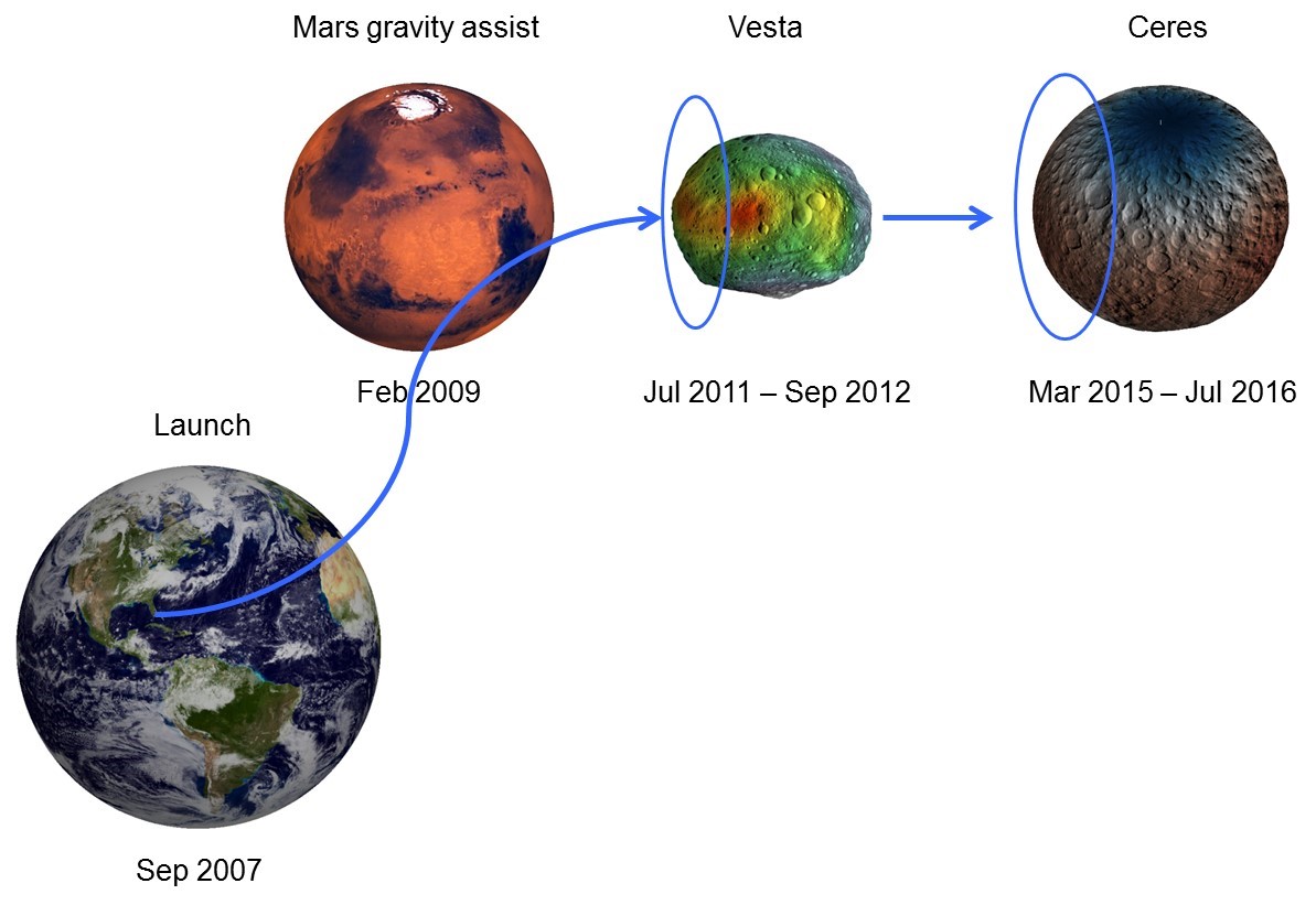
The Dawn spacecraft was launched on September 27, 2007 on a Delta II 2925- 9.5 Heavy from Cape Canaveral Air Force Station. Using its ion propulsion subsystem Dawn departed for Vesta, flying by Mars in February 2009. The spacecraft arrived at Vesta on July 16, 2011, performed its orbital operations there, and departing on September 5, 2012. Dawn arrived at Ceres on March 5, 2015, where Dawn orbited until the end of the baseline mission (Figure 1). The Dawn extended mission began July 1, 2016, with the spacecraft continuing its orbital operations at Ceres.
Dawn was an asteroid mapping mission. Each asteroid encounter was sub- divided into three mapping phases, each at different altitudes, and each with different science objectives and primary experiments. Shortly after orbit capture the spacecraft entered a survey altitude mapping orbit where the VIR instrument was primary. This phase was relatively short, lasting for only 6-7 orbits. Global spectroscopy data and low resolution global image mosaics were acquired during these phases at each asteroid. After survey, the spacecraft was maneuvered into a high altitude mapping orbit (HAMO) where the FC instrument was primary. Medium resolution global stereo imaging was performed at this altitude (950 km Vesta, 1950 km Ceres) while local high resolution spectroscopy data was acquired. Finally, the spacecraft proceeded to the low altitude mapping orbit (LAMO) where the GRaND and gravity experiments collected their prime data and additional, local, high resolution imaging and spectroscopy data were acquired. On asteroid approach, all of the instruments performed in-flight calibrations and acquired data that were used to characterize the hazards of the near asteroid environment (dust) and search for moons.
Chapter 2 describes the GRaND instrument, including its primary science objectives, detectors, electronics, operation, and calibration.
Chapter 3 describes the data sets, data volume, data processing and production, data flow, and scientific data validation.
Chapter 4 describes the archive volume generation, volume naming conventions, production, and PDS peer review.
Chapter 5 describes the PDS archive volume structure, the contents of each directory, and the various file naming conventions.
Chapter 6 describes the format of the EDR and RDR data files
Appendix A provides example PDS labels for the data files, index and geometry tables, and an example document label.
Appendix B lists the support staff and cognizant personnel associated with the archive generation and validation.
This specification applies to all archive volumes containing GRaND data products for the duration of its mission.
This document primarily describes the GRaND L-1A (EDR) and L-1B (RDR) archives. Higher order data products envisioned for GRaND are described by Prettyman et al. (2011). Level 2 products from Vesta encounter were developed by the Geochemistry team and archived by the PDS. The Level 2 products are based on studies published in the scientific literature (Prettyman et al., 2012; 2013; Lawrence et al., 2013; Peplowski et al., 2013, Yamashita et al., 2013). The Level 2 maps of Ceres were developed by Prettyman et al. (2017). The algorithm used to determine the Fe concentration map is described in the Supplementary Materials of Prettyman et al. (2017).
Planetary Science Data Dictionary Document, August 28, 2002, Planetary Data System, JPL D-7116, Rev. E
Planetary Data System Standards Reference, March 20, 2006, Version 3.7. JPL D- 7669, Part 2.
Planetary Data System Archive Preparation Guide, August 29, 2006, Version 1.1. JPL D-31224.
Dawn Science Data Management Plan, March, XX, 2007, DAWN-31-4032, JPL D-25901, Rev. A.
Lawrence D. J., Peplowski P. N., Prettyman T. H., Feldman, W. C., Bazell D., Mittlefehldt D. W., Reedy R. C., and Yamashita N. 2013. Constraints on Vesta's elemental composition: Fast neutron measurements by Dawn's gamma ray and neutron detector. Meteoritics & Planetary Science, doi:10.1111/maps.12187.
Peplowski P. N., Lawrence D. J., Prettyman T. H., Yamashita N., Bazell D., Feldman W. C., and Reedy R. C. 2013. Compositional variability on the surface of 4 Vesta revealed through GRaND measurements of high-energy gamma rays. Meteoritics & Planetary Science, doi:10.1111/maps.12176.Prettyman, T.H., W.C. Feldman, F. P. Ameduri, B. L. Barraclough, E. W. Cascio, K. R. Fuller, H. O. Funsten, D. J. Lawrence, G. W. McKinney, C. T. Russell, S. A. Soldner, S. A. Storms, Cs. Szeles, R. L. Tokar 2003, Gamma-ray and neutron spectrometer for the Dawn mission to 1 Ceres and 4 Vesta, IEEE Transactions on Nuclear Science Volume: 50, Issue: 4, 1, August 2003, pp. 1190-1197, DOI 10.1109/TNS.2003.815156.
Prettyman, T.H, W. C. Feldman, H. Y. McSween, R. D. Dingler, D. C. Enemark, D. E. Patrick, S. A. Storms, J. S. Hendricks, J. P. Morgenthaler, and K. M. Pitma 2011, Dawn's Gamma Ray and Neutron Detector, Space Sci. Rev., Vol. 163, pp. 371-459, DOI 10.1007/s11214-011-9862-0.
Prettyman T. H., Mittlefehldt D. W., Yamashita N., Lawrence D. J., Beck A. W., Feldman W. C., McCoy T. J., McSween H. Y., Toplis M. J., Titus T. N., Tricarico P., Reedy R. C., Hendricks J. S., Forni O., Le Corre L., Li J.-Y., Mizzon H., Reddy V., Raymond C. A., and Russell C. T. (2012), Elemental mapping by Dawn reveals exogenic H in Vesta's regolith, Science 388 242-246, http://dx.doi.org/10.1126/science.1225354
Prettyman, T. H., Mittlefehldt, D. W., Yamashita, N., Beck, A. W., Feldman, W. C., Hendricks, J. S., Lawrence, D. J., McCoy, T. J., McSween, H. Y., Peplowski, P. N., Reedy, R. C., Toplis, M. J., Le Corre, L., Mizzon, H., Reddy, V., Titus, T. N., Raymond, C. A., Russell, C. T. 2013. Neutron absorption constraints on the composition of 4 Vesta. Meteoritics & Planetary Science, doi: 10.1111/maps.12244.
Prettyman, T.H. and W.C. Feldman (2013), PDS data processing: Gamma Ray and Neutron Detector, Version 5.1, included in this volume (11-Jul-2013).
Prettyman, T.H. (2014a), Dawn's gamma ray and neutron detector: Ephemeris, pointing & geometry at Vesta, Version 1.0, included in this volume (28-Jul-2014).
Prettyman, T.H. (2014b), Remote sensing of chemical elements using nuclear spectroscopy, in T. Spohn, D. Breuer, & T. V. Johnson (Eds.), Encyclopedia of the Solar System, Elsevier (pp. 1161-1183). ISBN 9780124158450
Prettyman, T. H., N. Yamashita, M. J. Toplis, H. Y. McSween, N. Schorghofer, S. Marchi, W. C. Feldman, J. Castillo-Rogez, O. Forni, D. J. Lawrence, E. Ammannito, B. L. Ehlmann, H. G. Sizemore, S. P. Joy, C. A. Polanskey, M. D. Rayman, C. A. Raymond, C. T. Russell (2017), Extensive water ice within Ceres� aqueously altered regolith: Evidence from nuclear spectroscopy, Science 355 (6320), 55-59, doi: 10.1126/science.aah6765
Yamashita N., Prettyman T. H., Mittlefehldt D. W., Reedy R. C., Feldman W. C., Lawrence D. J., Peplowski P. N., McCoy T. J., Beck A. W., Toplis M. J., Forni O., Mizzon H., Raymond C. A., and Russell C. T. 2013. Distribution of iron on Vesta. Meteoritics & Planetary Science, doi:10. 1111/maps.12139.
Yamashita, N. and T.H. Prettyman (2014), Dawn's gamma ray and neutron detector: BGO data processing, Version 3.0, included in this volume (16-Sep-2014).
This specification is useful to those who wish to understand the format and content of the GRaND PDS data product archive collection. Typically, these individuals would be scientists, data analysts, or software engineers. Details of the archive can be found in the data set catalog files and Data Processing Documents, and Prettyman et al. (2011). An overview of the archive is provided here.
The Dawn Mission's Gamma Ray and Neutron Detector (GRaND) is a nuclear spectrometer that will collect data needed to map the elemental composition of the surfaces of 4-Vesta and 1-Ceres (Prettyman, et al., 2003; Prettyman et al., 2011). Results for Vesta are given by Prettyman et al. (2012, 2013), Lawrence et al. (2013), Peplowski et al. (2013) and Yamashita et al. (2013). GRaND measures the spectrum of planetary gamma rays and neutrons, which originate from cosmic ray interactions and radioactive decay within the surface, while the spacecraft (S/C) is in orbit around each body. The instrument, which is mounted on the +Z deck of the spacecraft, consists of 21 sensors designed to separately measure radiation originating from the surface of each asteroid and background sources, including the space energetic particle environment and cosmic ray interactions with the spacecraft. The nuclear spectroscopy data provided by GRaND will be analyzed to determine the abundance of major, rock forming elements, such as O, Mg, Si, Al, Ca, Ti, and Fe; incompatible elements, including K and Th, detected by gamma ray emissions from the decay of long-lived radioisotopes; and H, C, N, and Cl, which are constituents of ices and products of aqueous alteration of silicate minerals.
Scientific objectives include:
Nuclear spectroscopy is used to determine the elemental composition of planetary surfaces and atmospheres [e.g. see Prettyman (2014b) for general review of gamma ray and neutron measurement principles]. Radiation, including gamma rays and neutrons, is produced steadily by cosmic ray bombardment of the surfaces and atmospheres of planetary bodies and by the decay of radionuclides in the regolith. The leakage flux of gamma rays and neutrons contains information about the abundance of major elements, selected trace elements, and ice constituents (e.g., H, C, and N) as well as elements associated with aqueous alteration products such as Cl. Gamma rays and neutrons can be measured at altitudes less than a planetary radius, enabling global mapping of elemental composition by an orbiting spacecraft. Radiation that escapes into space originates from shallow depths (< 1 m within the solid surface). Consequently, nuclear spectroscopy is complementary to other surface mapping techniques, such as reflectance spectroscopy, which is used to determine the mineralogy of planetary surfaces. The main benefit of gamma ray and neutron spectroscopy is the ability to reliably identify elements important to planetary geochemistry and to accurately determine their abundance. This information can be combined with other remote sensing data, including surface thermal inertia and mineralogy, to investigate many aspects of planetary science.
Nuclear reactions and radioactive decay result in the emission of gamma rays with discrete energies, which provide a fingerprint that can uniquely identify specific elements in the surface. Depending on the composition of the surface, the abundance of major rock-forming elements such as O, Mg, Al, Si, Cl, Ca, Ti, Fe, as well as Cl, a tracer of aqueous alteration, H, and elements with radioisotopes (40K, U series, Th series) can be determined from measurements of the gamma ray spectrum when they are present in detectable quantities. High energy neutrons produced by cosmic ray interactions loose energy in successive collisions with nuclei in the regolith, and are ultimately absorbed or escape into space. Their sensitivity to elemental composition depends on three main types of reactions that are important in three broad energy ranges measured by GRaND: inelastic scattering (important for fast neutrons greater than about 0.7 MeV); elastic scattering (epithermal neutrons between 0.1 eV to 0.7 MeV); and absorption (thermal neutrons less than 0.1 MeV). Fast neutrons are sensitive to the average atomic mass of the regolith when H is present in small quantities (H weight fractions less than a few hundred ppm). Epithermal neutrons are very sensitive to the abundance of H and are relatively insensitive to variations in the abundance of major elements. Thermal neutrons are sensitive to strong absorbers such as Fe, Ti, N, Cl, Gd, and Sm.
Close proximity to the planetary body is needed to measure neutrons and gamma rays because their production rate is relatively low in comparison, for example, to reflected sunlight. In addition, sensors used for gamma ray and neutron spectroscopy are generally insensitive to incident direction. Consequently, spatial resolution depends on orbital altitude, and higher resolution can be achieved by moving closer to the planet. Regional scale measurements are generally made using nuclear spectroscopy, in contrast to the meter to kilometer scale generally achieved by reflectance- and thermal emission-spectroscopy.
GRaND uses scintillator- and semiconductor-based radiation sensors to detect neutrons and gamma rays as well as energetic particles from the space environment. A scintillator is a transparent material that converts the kinetic energy of charged particles (such as electrons produced by gamma ray interactions or alpha particles and recoil protons produced by neutron reactions) into flashes of light detectable by a photomultiplier tube or photodiode. Semiconductors can be used to detect gamma rays. Swift electrons produced by Compton and photoelectric interactions ionize the semiconductor, producing electron-hole pairs. The electrons and holes drift under the influence of an applied electric field to electrical contacts. As they drift, the electrons and holes induce charge on the contacts, which can be measured by a charge-sensitive preamplifier. The amplitude of the charge pulse is proportional to the energy deposited by the gamma ray, which enables semiconductors to be used for spectroscopy
The sensors and shielding/structural materials of GRaND were arranged to distinguish gamma rays and neutrons originating from the target body from those from background sources, including neutrons and gamma rays produced by cosmic rays in the bulk spacecraft, and energetic particle interactions with the instrument. The sensors on GRaND were selected to operate between -20° C and 30° C and do not require active cooling.
GRaND uses four types of radiation sensors, which are shown in the cutaway diagram of the instrument in Figure 2 (their energy ranges are summarized in Table 5):
1. Bismuth germinate (BGO) scintillator: A 7.6 (X) cm x 7.6 (Y) cm x 5.08 (Z) cm BGO crystal (approximately 300 cm3 volume) is located in the center of the scintillator subassembly. The scintillator is coupled to a 5.08 cm diameter photomultiplier tube. BGO has high density and high atomic number and is sensitive to gamma rays over a wide energy range (up to 10 MeV). The pulse height resolution at room temperature is approximately 10% full-width-at- half-maximum (FWHM) at 662 keV.2. Cadmium Zinc Telluride (CZT) semiconductor: A planar array of 4 x 4 CZT crystals is positioned on the +Z side of the BGO crystal (Figure 2), which faces towards the asteroid during science mapping. Each crystal is 10 mm x 10 mm x 7 mm. Consequently, the array has a sensitive volume of 11.2 cm3. Coplanar grids are used to mitigate the effects of hole trapping, resulting in excellent peak shape and pulse height resolution over a wide range of energies. The pulse height resolution was better than 3% FWHM at 662 keV during laboratory testing. The array was designed to measure gamma rays with energies up to 3 MeV. The relatively high energy resolution of the CZT array enables accurate measurement of gamma rays in the densely-populated, low energy region of the spectrum, which contains gamma rays from radioactive decay and cosmic-ray induced reactions within the surface of the asteroid
3. B-loaded plastic scintillator: Two L-shaped boron-loaded plastic (BLP) scintillators (each 193 cm3) are located on the -Y and +Y sides, surrounding the sides of the BGO crystal and CZT array. The scintillators act as an anticoincidence shield to reject cosmic ray interactions. In addition, the scintillators are sensitive to neutrons. Fast neutrons (with energies greater than 700 keV) can undergo elastic scattering with H within the plastic to produce knock-on protons, which ionize the scintillator, resulting in the production of detectable light. In addition, thermal and epithermal neutrons can be captured via the 10B(n,α)7Li* reaction to produce 93 keVee light output. Note that the subscript 'ee' indicates an electron-equivalent energy, corresponding to the energy a swift electron would need in order to produce the same light output as the reaction products. The reaction product, 7Li*, produces a 478 keV prompt gamma ray. Fast neutrons with energies greater than 700 keV produce a characteristic double pulse signature, corresponding to light output from fast-neutron proton recoils followed later by neutron capture with 10B after the neutron has thermalized. The amplitude of the first pulse is related to the energy of the incident neutron. Thermal and epithermal neutrons also produce a unique coincidence signature, corresponding to 93 keVee of light produced in the plastic in coincidence with 478 keV deposited in the BGO crystal.
4. Li-glass, B-loaded-plastic phosphor sandwich (phoswich): Two BLP scintillators are located on the nadir (+Z) and spacecraft (-Z) sides of the instrument, centered on the CZT array and BGO crystal. Each BLP scintillator is approximately 10.16 cm x 10.16 cm x 2.54 cm (264 cm3) and is read out by a 2.54 cm diameter phototube. With the exception of the outward-facing side, each scintillator is covered with a sheet of Gd foil, which absorbs thermal neutrons. The outward facing side is covered by a plate of lithiated glass, 0.2 cm thick. The lithiated glass is optically-coupled to the BLP such that the phototube measures light produced in both the glass and the plastic. 6Li is a strong thermal neutron absorber. Consequently, the BLP is shielded from thermal neutrons. Epithermal neutrons that undergo capture via the 10B(n,α) reaction in the BLP produce 93 keVee. Thermal and epithermal neutrons can undergo neutron capture via the 6Li(n,t) reaction, which produces approximately 340 keVee, and is seen as a separate peak in the pulse height spectrum. Consequently, the thermal neutron signature can be determined by the weighted difference between the counting rates observed for the two reactions. Fast neutrons are measured using the double pulse signature in the BLP. In addition, the (n,γ) BLP-BGO coincidence signature provides a low-background measurement of epithermal neutrons.
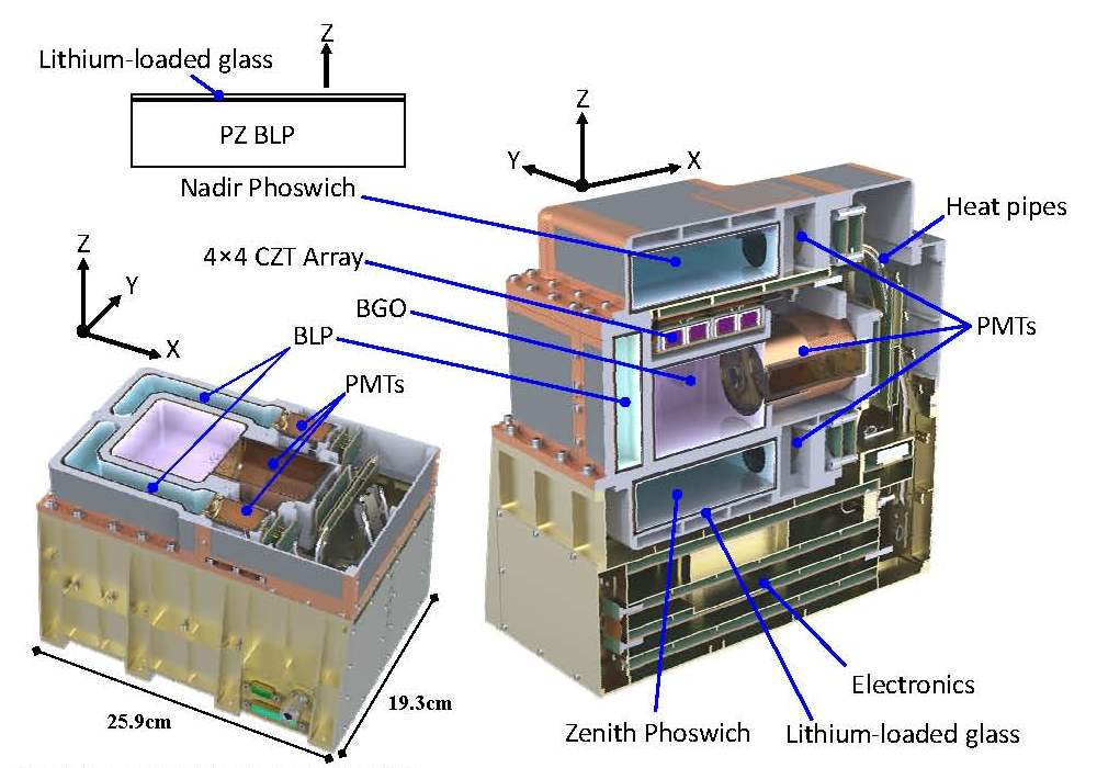
FIGURE 2. Cutaway views of GRaND
Cutaway views of GRaND show the placement of subsystems and components (an XY cut is shown left and a XZ cut is shown right). The coordinate system for GRaND is the same as that of the spacecraft. GRaND is mounted on the (+X, +Y) corner of the +Z deck of the spacecraft (Figure 3). During mapping at Vesta and Ceres, the body center is in the +Z direction. The instrument coordinate system determines the naming convention of the sensors and orientation of the instrument relative to the spacecraft. The use of MZ indicates a sensor on the -Z (spacecraft-facing during mapping) side of GRaND; PZ indicates the sensor is on the +Z (asteroid when pointing nadir) side; MY indicates the sensor is on the -Y side (inboard) side of the instrument; and PY indicates the sensor is on the +Y side (outboard, towards the +Y solar panel) side of the instrument. The phototube assembly, labeled 'PMTs' in the figure, points along the +X axis (towards the high gain antenna). A detailed diagram of the sensor layout is provided in Prettyman et al. (2011). Artwork courtesy S. Storms of Los Alamos National Laboratory.
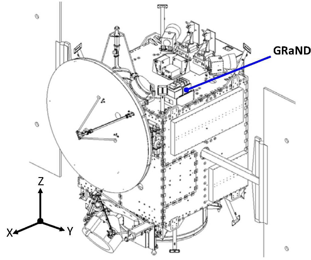
FIGURE 3. Location of GRaND
GRaND is mounted on the (+X, +Y) corner of the +Z deck of the spacecraft. During mapping at Vesta and Ceres, the body center is in the +Z direction.
Table 5. Approximate energy range and pulse height resolution of GRaND sensors at nominal high voltage settings.
   --------------------------------------------------------------------------------------
   Sensor       ADC bits(1)   Energy        keV per   Energy          Threshold
                              range (MeV)   channel   resolution
   --------------------------------------------------------------------------------------
   +/-Z phos.    8            0 to 2.55     10        20%(2)/40%(3)   20 keV(4)/50 keV(5)
   +/-Y BLP      8            0 to 2.55     10        40%(3)          20 keV(4)/50 keV(5)
   BGO          10            0 to 10       10        10.5%(6)        300 keV
   CZT          11            0 to 4         2        3%(6)           300 keV
   --------------------------------------------------------------------------------------
   (1) 12-bit ADCs are used for all sensors. The maximum number of high-order
       bits used is given.
   (2) Percentage full width at half maximum (FWHM) of the 260 keVee
       6Li(n,t)4He reaction peak.
   (3) Percentage FWHM of the 93 keVee 10B(n,α)7Li
       reaction peak.
   (4) Prompt threshold;
   (5) delayed threshold (second interaction for fast neutrons).
   (6) Percentage FWHM at 662 keV (gamma rays from a 137Cs source).
       Note that the pulse height resolution of the CZT sensors has gradually
       degraded in flight from the quoted value due to radiation damage
       (Prettyman et al., 2011).
An electronics block diagram of GRaND is shown in Figure 4. GRaND derives power from the S/C 28Vdc power bus. The instrument low voltage power supply provides +/-5V to all the digital and analog circuits and +12V to all high voltage power sources, which supply 0 to +1500V to the photomultiplier tubes and -1500V/+70V to the CZT sensors. The instrument transmits and receives data through an RS-422 interface. The instrument is controlled by a UTMC micro-controller, which manages instrument subsystems, processes commands, monitors state of health (SOH), and processes the science data. Each of the radiation sensors is read out by analog front-end electronics, which provides shaped pulses, which are digitized by analog-to-digital-converters (ADC) to determine pulse amplitude, and timing signals for analysis of coincident events. Signals from the FEE are processed by an Actel field-programmable-gatearray (FPGA). The FPGA categorizes signals from the sensors, identifying patterns that correspond to important events (for example, the fast neutron double-pulse signature). SOH data are recorded in the engineering telemetry, including high voltage values and temperatures. Commandable parameters include instrument high voltage settings, parameters used to classify coincidence events, and measurement intervals.
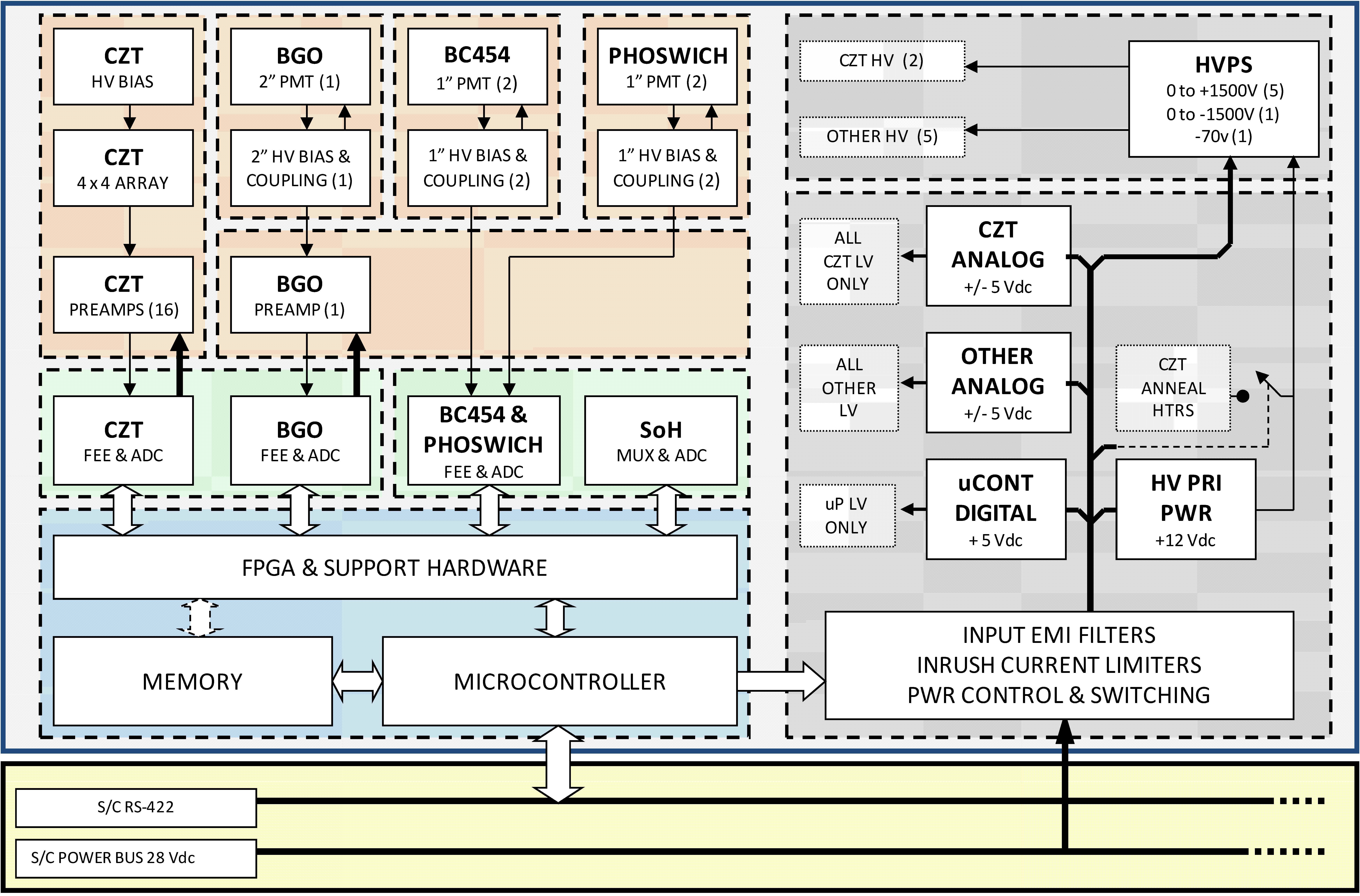
FIGURE 4. Instrument electronics block diagram
Each science record sent by GRaND contains counting data acquired during a collection interval, which is set by the commandable parameter TELREADOUT. The collection intervals are successive, forming a time series that can be analyzed to map elemental abundances. The records are time-tagged with the spacecraft clock (SCLK) value, which can be merged with NAIF/SPICE ephemeris data for mapping. Each science record includes scaler data, event data, and histograms. The pattern of pulses recorded by the sensors for each radiation interaction is processed by the FPGA, which categorizes the events. The events are scaled and binned into histograms. In addition, a subset of neutron and gamma ray events are recorded in a fixed length buffer. At the end of each collection interval, the data are compressed, packetized, and transmitted. The event categories recorded by GRaND are as follows (Note that event categories 3, 5, 6, and 8 were deleted during instrument development):
Category 1 (CAT1): A single pulse from the -Z or +Z phoswich. CAT1 data are binned into a histogram (256 channels) which can be analyzed to determine the areas of peaks corresponding to the 93 keVee 10B(n,α) and the 340 keVee 6Li(n,t) reactions.
Category 2 (CAT2): A prompt coincidence between the BGO and any one of the four BLP scintillators. The objective is to record thermal and epithermal neutron interactions by detecting the prompt coincidence between the deposition of 93 keVee by the 10 B(n, α)7Li* reaction products in the BLP and full energy deposition of the associated gamma ray from 7Li* → 7Li + γ, where 7Li* denotes the first excited level of 7Li. If a coincidence is detected, the FPGA checks to see if the pulse height recorded by the BGO is within a commandable coincidence window, set to bracket the 478 keV full energy peak. If so, then the pulse recorded by the BLP is binned into a 64-channel histogram that contains the 93 keVee reaction peak. Redundantly, the FPGA also checks to see if the pulse height recorded by the BLP is within a commandable coincidence window set to bracket the 93 keVee peak. If so, then the pulse recorded by the BGO is binned in a 64-channel histogram that contains the 478 keV full energy peak. Consequently, two 64channel spectra are recorded for each BLP. Since the +/-Z BLP scintillators are shielded by Gd and Li-glass, the areas of the 93 keVee and 478 keV peaks in the 64-channel histograms recorded by the CAT2 process for these two scintillators are sensitive to epithermal neutrons. The CAT2 signature for the side scintillators, which are unshielded, is sensitive to both thermal and epithermal neutrons.
Category 4 (CAT4): A double-pulse occurring in any one of the phoswich or BLP scintillators. To reduce after-pulsing, events for which the second events occur within 400 ns are rejected. The maximum time to the second pulse (TTSP) recorded by GRaND is 25.6 microseconds. The amplitudes of the first and second pulse and the TTSP are recorded as list mode data in a fixed length buffer. The total number of CAT4 events processed by the FPGA during the collection interval is recorded in the scaler data. The CAT4 data can be analyzed to determine the flux and energy distribution of fast neutrons.
Category 7 (Cat7): A coincidence between a single CZT sensor and the BGO scintillator. The CZT pulse height (digitized by a 12-bit ADC) and CZT-sensor- ID are recorded as event data in the gamma event buffer. The BGO pulse height is recorded as a 9 bit unsigned integer. The portion of the gamma event buffer reserved for CAT7 events is commandable. The CAT7 data can be used to discriminate gamma rays originating from the target body and the spacecraft. For example, gamma rays originating from the target body (from nadir) can undergo low angle Compton scattering in a CZT sensor prior to entering the BGO crystal, where they may deposit the rest of their energy. The energy of the gamma ray can be determined by summing the pulse heights measured by the CZT and BGO sensors. Gamma rays originating from the spacecraft are shielded from the CZT array by the BGO crystal. In addition, those originating from the spacecraft that interact with a CZT sensor must scatter through a large angle, depositing a relatively large amount of energy in the CZT sensor before reaching the BGO crystal. Consequently, summing the energy deposited in the CZT and BGO sensors for events in which the energy deposited in the BGO sensor is greater than the energy deposited in the CZT sensor tends to reject gamma rays originating from the spacecraft.
Category 9 (CAT9): A single pulse from the BGO scintillator. The CAT9 events are recorded as a 1024 channel pulse height spectrum.
Category 10 (CAT10): A single interaction with a CZT sensor, in which one of the 16 CZT sensor records a pulse and none of the other sensors on GRaND (including BGO, BLP, etc..) are triggered. The pulse height (digitized by a 12- bit ADC) and CZT-sensor-ID are recorded as list-mode data in a fixed length buffer. The total number of CAT10 events processed by the FPGA during the collection interval is recorded in the scaler data. The CAT10 list mode data can be processed, given the known energy calibration for each of the sensors, to form a composite pulse height spectrum. During mapping, the CAT9 histogram and CAT10 composite spectrum contain full energy peaks corresponding to radioactive decay and nuclear reactions occurring within the planetary surface, which can be analyzed to determine elemental abundances.
Summary of Event Categories
--------------------------------------------------------------------------------
CAT1   A single pulse from either the �Z or +Z phoswich recorded in 256-channel
       histograms. Sensitive to thermal and epithermal neutrons.

CAT2   Coincidence between the any of the four BLP scintillators and the BGO
       sensor. Pairs of 64-channel histograms are recorded for each BLP-BGO
       combination (e.g. +Z phoswich � BGO).  Sensitive to thermal and
       epithermal neutrons.

CAT4   Double pulse in the BLP sensors. The amplitude and ID of the BLP sensor
       for the first and second pulses is recorded along with the time between
       pulses in the neutron event buffer.  Sensitive to fast neutrons.

CAT7   Coincidence between the BGO and any one of the 16 CZT sensors.  The CZT
       pulse amplitude, sensor ID, and the BGO pulse amplitude are recorded in
       the gamma event buffer.  Useful, for example, for pair spectroscopy.

CAT9   A single pulse from the BGO sensor binned into a 1024-channel histogram.
       Sensitive to gamma rays up to about 10 MeV.

CAT10  A single pulse from any one of the 16 CZT sensors.  The pulse amplitude
       and sensor ID is recorded in the gamma event buffer along with the CAT7
       data. The only distinguishing characteristic between CAT7 and CAT10 is
       that the BGO pulse amplitude is greater than 0 for CAT7 and 0 for CAT10.
       Sensitive to gamma rays up to about 3 MeV.
--------------------------------------------------------------------------------
GRaND has three operational modes:
1. STANDBY;
2. NORMAL; and
3. ANNEAL.
The instrument starts in STANDBY mode. In STANDBY mode, the radiation sensors are not operational (all commands are accepted except high voltage enable commands). Only SOH data are generated in standby mode. Data from the temperature sensors are recorded in STANDBY if the +/-5V low voltage supply is activated. From STANDBY, the instrument can be commanded to NORMAL mode for which all commands are accepted. In NORMAL mode, the instrument can be configured for science data acquisition, including enabling and setting the high voltage level for each sensor. Both SOH and science data are included in the telemetry. From STANDBY, the instrument can also be commanded to ANNEAL mode, which is designed to anneal radiation damage accrued by the CZT crystals (Prettyman et al., 2003). Only SOH data are generated in ANNEAL mode.
Science data will be acquired by GRaND during cruise, Mars Flyby, and mapping of Vesta and Ceres. In order to acquire science data, GRaND must be in NORMAL mode with high voltages turned on and adjusted to nominal settings. Large gaps in the data are expected during cruise, when the instrument is off. For science mapping, only data acquired when the instrument bore-sight is pointed to within 5-deg of body center are used. In addition, solar energetic particle events are reported separately from data acquired during quiet conditions. Contamination from other instruments and spacecraft subsystems appears to be negligible, but will be evaluated throughout the mission.
Calibration data for GRaND were acquired during assembly, test, and launch operations (ATLO), before and after delivery of the instrument for integration with the spacecraft. Prior to delivery, the instrument was characterized at a calibration facility at Los Alamos National Laboratory and on the bench using neutron and gamma ray sources. The main goals of the calibration exercise were to verify the functionality of each of the sensors; determine the energy calibration for each sensor and event category; determine the absolute calibration (relationship between flux and counting rate) for each sensor and event category as a function of incident energy and direction. Data acquired during comprehensive performance tests (CPTs) following integration of GRaND with the spacecraft provide supplemental information needed to confirm the energy calibration.
Data acquired by GRaND during cruise and Mars Gravity Assist are useful for instrument calibration as well as characterization of the energetic particle background during periods of low solar activity, which are representative of data used for mapping (solar energetic particle events are excluded). The close fly by of Mars by Dawn provided a valuable data set that can be compared directly to data acquired by the Mars Odyssey Gamma Ray and Neutron Spectrometer subsystems, enabling cross-calibration of GRaND with Mars Odyssey (see Prettyman et al., 2011 for details). Cruise data acquired before and after encounters with Ceres and Vesta will be used to assess the buildup of induced radioactivity with GRaND, if detectable.
The structure and content of the Level 1A and 1B data sets are described in detail in their respective catalog files. Data processing steps as well as a thorough presentation of the data products are described in Prettyman et al. (2011) and in Data Processing Documents for the EDR and each RDR data set.
A summary of data files included in the Level 1A and 1B archives are provided in the following table:
Table 6. Standard Data Products

--------------------------------------------------------------------------------
Data Set ID  |Standard        |Standard Product Description
             |Data            |
             |Products        |
--------------------------------------------------------------------------------
             |AUX_RDG         |Instrument readings file: a time-ordered list of
             |                |temperature and voltage readings averaged over
             |                |each state-of-health accumulation interval
             |                |(TELSOH), converted to physical units.
             |------------------------------------------------------------------
             |AUX_SCI-SCL     |Science scaler data: a time-ordered list of the
             |                |scaler data recorded in the science telemetry.
             |                |The accumulation interval for the scalers is
             |                |TELREADOUT.
             |------------------------------------------------------------------
             |AUX_SOH-SCL     |State of health scaler data: a time-ordered list
             |                |of the scaler data recorded in the state-of-
             |                |health telemetry. The accumulation time for the
             |                |scaler data is TELSOH. Note that the scalers are
             |                |reset at the end of each science accumulation
             |                |interval (TELREADOUT). If the state-of-health
             |                |accumulation interval is selected to subsample
             |                |the science interval, then the state-of-health
DAWN-X-      |                |scalers can be used to detect and correct for
GRAND-2-EDR- |                |rollover of the science scalers, such as the dead
CRUISE-      |                |time counter.
COUNTS-V1.0  |------------------------------------------------------------------
             |AUX_STA         |Instrument state file: the instrument settings,
or           |                |including the mode, power supply states, high
             |                |voltage settings, the data accumulation interval,
DAWN-M-      |                |and coincidence windows. The first record of the
GRAND-2-EDR- |                |state-of-health file is recorded in the state
MARS-        |                |file, stamped with SCET UTC. Thereafter, rows are
COUNTS-V1.0  |                |added only when the instrument settings change.
             |------------------------------------------------------------------
             |GAMMA_BGO       |time-ordered list of pulse height spectra (1024
             |                |channels with units of uncorrected
             |                |counts/channel) acquired by the BGO sensor
             |------------------------------------------------------------------
             |GAMMA_EMG       |gamma ray event data as a binary time series
             |------------------------------------------------------------------
             |NEUTRON_BG02_MY |time-ordered lists of the 64-channel CAT2 BGO
             |                |pulse height spectra for coincidences with the
             |                |BGO and the BLP �Y sensor
             |------------------------------------------------------------------
             |NEUTRON_BG02_PY |time-ordered lists of the 64-channel CAT2 BGO
             |                |pulse height spectra for coincidences with the
             |                |BGO and the BLP +Y sensor
             |------------------------------------------------------------------
             |NEUTRON_BG02_MZ |time-ordered lists of the 64-channel CAT2 BGO
             |                |pulse height spectra for coincidences with the
             |                |BGO and the BLP �Z sensor
             |------------------------------------------------------------------
             |NEUTRON_BG02_PZ |time-ordered lists of the 64-channel CAT2 BGO
             |                |pulse height spectra for coincidences with the
             |                |BGO and the BLP +Z sensor
             |------------------------------------------------------------------
             |NEUTRON_BLP2_MY |time-ordered lists of the 64-channel CAT2 BLP
             |                |pulse height spectra for coincidences with the
             |                |BGO and the BLP �Y sensors
             |------------------------------------------------------------------
             |NEUTRON_BLP2_PY |time-ordered lists of the 64-channel CAT2 BLP
             |                |pulse height spectra for coincidences with the
             |                |BGO and the BLP +Y sensor
             |------------------------------------------------------------------
             |NEUTRON_BLP2_MZ |time-ordered lists of the 64-channel CAT2 BLP
             |                |pulse height spectra for coincidences with the
             |                |BGO and the BLP �Z sensor
             |------------------------------------------------------------------
             |NEUTRON_BLP2_PZ |time-ordered lists of the 64-channel CAT2 BLP
             |                |pulse height spectra for coincidences with the
             |                |BGO and the BLP +Z sensor
             |------------------------------------------------------------------
             |NEUTRON_EMN     |the neutron event data as a binary time series.
             |------------------------------------------------------------------
             |NEUTRON_PHOS_MZ |time-ordered lists of the 256-channel CAT1 pulse
             |                |height spectra for the -Z phoswiches. Note that
             |                |the naming convention for the top, bottom, and
             |                |side scintillators is determined by the
             |                |instrument coordinate system.
             |------------------------------------------------------------------
             |NEUTRON_PHOS_PZ |time-ordered lists of the 256-channel CAT1 pulse
             |                |height spectra for the +Z phoswiches. Note that
             |                |the naming convention for the top, bottom, and
             |                |side scintillators is determined by the
             |                |instrument coordinate system.
--------------------------------------------------------------------------------
             |-TSI-EPM*       |time series of ephemeris and pointing data,
             |                |including the total livetime, the distance and
             |                |direction to body center, the velocity of the
             |                |spacecraft rotated into the reference frame of the
             |                |instrument, the subsatellite position and
             |                |altitude, and the fractional solid angle subtended
             |                |by the body at the spacecraft. In addition, the
             |                |average counting rate for the 'coincidence of
             |                |three or more sensors' scaler (SCALER_SCI[15]) is
             |                |provided as an indicator of the interaction rate
             |                |of galactic cosmic rays.
DAWN-M-      |------------------------------------------------------------------
GRAND-2-RDR- |-TSI-NCR        |time series of neutron counting rates determined
MARS-COUNTS- |                |from CAT1, CAT2, and CAT4 pulse height spectra.
V1.0         |                |Counting rates sensitive to neutrons in the
             |                |thermal, epithermal, and fast energy ranges are
             |                |provided. Propagated uncertainties (1-sigma) are
             |                |provided.
             |------------------------------------------------------------------
             |-TSI-GCR        |time series of net areas for selected full energy
             |                |interaction peaks from the pulse height spectrum
             |                |acquired by the BGO sensor. Propagated
             |                |uncertainties (1-sigma) are provided.
             |------------------------------------------------------------------
             |-TSI-BGO        |time series of BGO 1024-channel pulse height
             |                |spectra that have been adjusted so that the
             |                |offset is 0 keV with a slope of 8.9 keV/channel.
             |                |Note that the method for determining the
             |                |uncertainty in the counting rates for each channel
             |                |is provided in the format file.
--------------------------------------------------------------------------------
             |-EPG            |time series of spacecraft ephemeris, pointing,
             |                |and measurement geometry (EPG) for each and every
             |                |science data record acquired by GRaND during
             |                |Vesta encounter.  The time series includes live
             |                |time, instrument configuration, and the triples
             |                |counting rate, used as a proxy for the galactic
             |                |cosmic ray flux.  The spacecraft clock (SCLK) is
             |                |used as a serial number to cross reference EPG
DAWN-A-GRAND-|                |information with science data in EPG and RDR
2-RDR-VESTA- |                |files.
COUNTS-V1.0  |------------------------------------------------------------------
             |-PHS-BGOC       |time series of corrected and energy calibrated
             |                |BGO pulse height spectra for suitable for use in
             |                |geochemical studies (elemental ID and
             |                |quantification).
--------------------------------------------------------------------------------
*TSI refers to the type of time series: central moving average (CMA) or decimated time series (DTS). As described in Prettyman and Feldman (2010), the Level 1b data are represented as a time series in which counting rates and spectra are averaged over a time-window, consisting of an odd number of science accumulation intervals, selected by the evaluator. Two types of time series are possible: a CMA, in which the averaging window is centered on each point in the original time series, and a result is reported for each science accumulation interval; and a DTS, in which the averaging window is shifted forward in time by its width, resulting a data set that has fewer points than the original time series. The CMA is intended for mapping, for example, in cases where full sampling of rapidly changing counting rates and solid angles is needed. The DTS is useful for averaging over long periods of time, for example, during cruise, when counting rates are not changing rapidly. By averaging over long time intervals, the DTS can be used to produce high precision gamma ray spectra needed for accurate peak identification, analysis, and calibration.
Level 2 maps of Vesta�s composition were developed by the Dawn Geochemistry team. These were submitted to the PDS and have been certified. Maps include the abundance of H, Fe, thermal, epithermal, fast, and high-energy- gamma-ray counting rates. Level 2 maps of Ceres include the concentrations of H and Fe and the uncorrected and correcting counting data from which the concentrations were derived. The data reduction and analysis methods are described by Prettyman et al. (2017), Supplementary Materials..
The DSC captures all of the payload instrument telemetry frames as binary files after the data have been cleaned up in the post-pass processing (reconstructed level-0 data). Post-pass processing is completed with 8 hours of each pass and typically is able to fix minor form of data corruption (partial packet reconstruction, dropped time tags, etc.). These files are inventoried within the Dawn Science Database (DSDb) and made available to the teams for download at any time. The DSC prepares the documentation and metadata required in order to submit these products to the PDS to be saved (rather than archived). The PDS documentation threshold for saved data sets is substantially lower than for archived products. The raw decoded frames are not considered to be useful for the general science community but the bits will be preserved in their rawest form. The DSC will submit the telemetry frames to the PDS Small Bodies Node (SBN) within a week of the end of each science phase. All level-0 data products are created with PDS 'minimum' labels. Each level-0 data file contains the CCSDS packets for a single APID.
The Doppler Tracking data are used by the NAV and Gravity Science teams and do not flow into the TDS. These data flow from the DSN into the OSCAR-X system where they are accessible to the gravity team at JPL. Since these data do not flow directly into the DSC, the DSC staff will manually retrieve them from OSCAR-X and load them into the DSDb. Gravity Science investigators that are not at JPL will use the DSDb to retrieve the level-0 data for their analysis. This process is described in the operational interface agreement (OIA-DSC-409) between the Gravity Science Team and the DSC. Unlike the decoded frames, the level-0 Doppler Tracking data are archived with the PDS. DSC prepares these data for archive and submits them to the PDS SBN at the same time as the level-1A data products from the payload instruments.
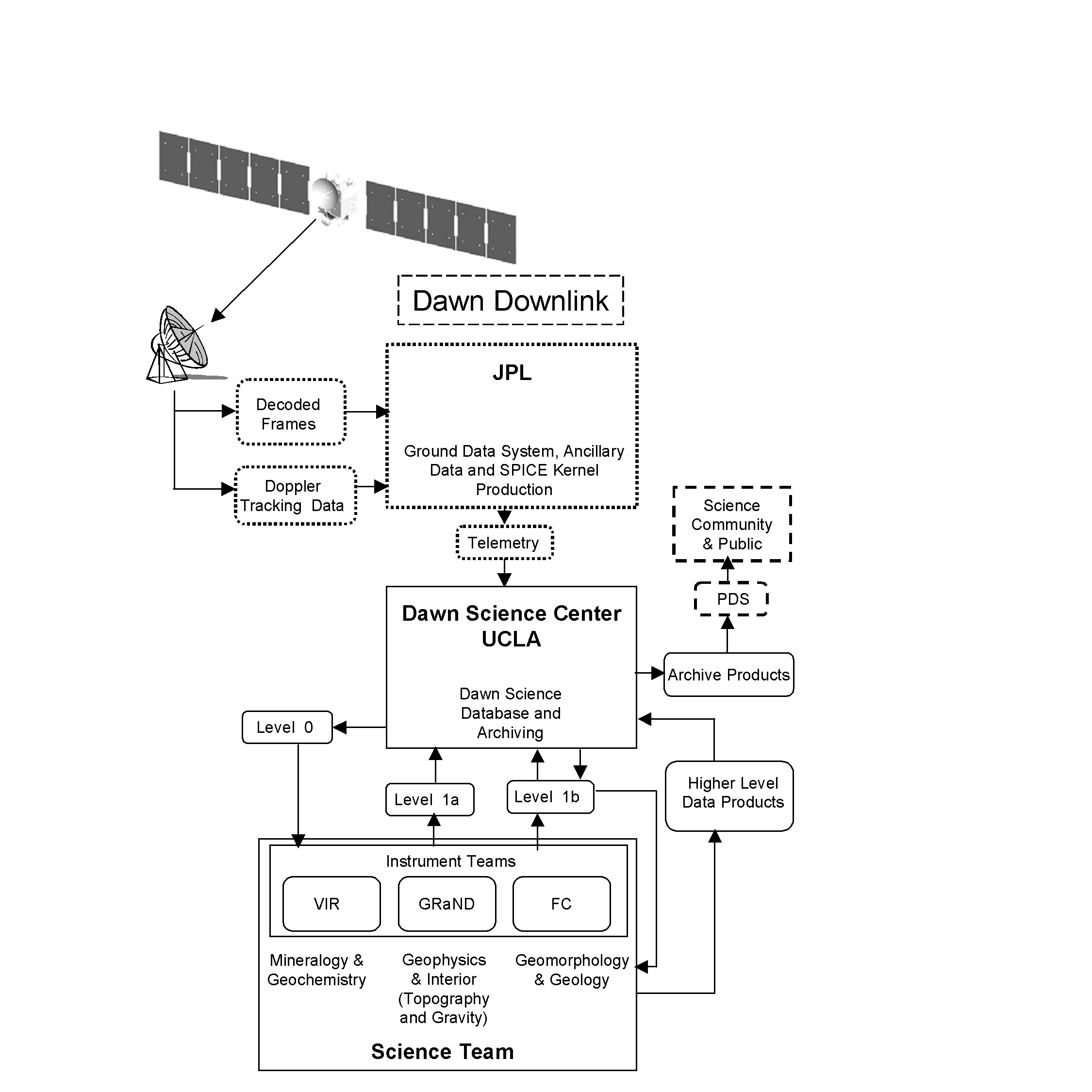
Figure 5 Dawn Science Data Flow. SPAA elements and products are outlined with solid black lines, MOS components with dotted lines, and PDS components with dashed lines.
The GRaND Level 1 data processing steps are described in detail in Prettyman et al. (2011) and the Data Processing Document included in this archive.
The GRaND EDR are a time-ordered collection of gamma ray and neutron counting data and histograms acquired by GRaND during different phases of the Dawn Mission, including assembly-test-and-launch-operations (ATLO), cruise, Mars Gravity Assist (MGA), and science mapping at 4-Vesta and 1-Ceres. The dataset also includes state-of-health data (instrument settings, temperature and voltage readings) needed for scientific analysis of the neutron and gamma ray data. The EDR is an intermediate data product (Level 1A) that is derived from Raw Data Records (Level 0) using reversible operations. The Level 1A data are the lowest level of GRaND data archived in the PDS, from which all higher order data sets are derived. To support timely delivery of higher order products, the Level 1A data are processed using an automated pipeline, which operates on Level 0 data when it is queried by the DSC.
The data set consists primarily of ASCII tables, divided into three functional categories: auxiliary information (AUX); gamma ray spectra and event data (GAMMA); and neutron spectra and event data (NEUTRON). Gamma ray and neutron event data are recorded in binary files. Some of the data in the ASCII files, which are human-readable, are repeated in the binary files to aid in the verification of user-written routines.
The Level 1A data are automatically processed using a pipeline, which operates on files queried by the DSC over selected time intervals. Each DSC query separates the GRaND data into files containing state-of-health and science data records, in the order in which they were received on the ground and with corrupted packets removed. The state-of-health data are further divided into real time telemetry data and playback data. The science data are stored in a single raw data file.
The pipeline merges the state-of-health data from the playback and realtime files to produce a time-ordered-list of records. Selected data are extracted to produce the Level 1A AUX files. Internal temperature readings are converted from data numbers (DN) to engineering units using a linear function determined during ground calibration: T (degrees C) = 0.4354 DN - 32.267. The high voltage readings for the high voltage power supplies are reported in engineering units using the conversion V (Volts) = 1500 DN/255. The CZT differential bias voltage is converted using V (Volts) = 0.405 DN.
The science data are decompressed, decoded, separated by functionality and written as time-ordered ASCII tables and binary time series. The raw histograms (CAT1, CAT2, and CAT9) are represented as 8 bit numbers which are decompressed and reported as 16 bit, unsigned integers.
The GRaND Reduced Data Records (RDR) are a time-ordered collection of corrected gamma ray and neutron counting data and calibrated pulse height spectra acquired by GRaND during Mars Gravity Assist (MGA). Similar products will be developed for science mapping at 4-Vesta and 1-Ceres and for data acquired during cruise. The RDR is a calibrated data product (Level 1B) that is derived from Experimental Data Records (EDR, Level 1A). The objective of the RDR is to provide counting rates and ancillary pointing and ephemeris data needed for mapping. The ancillary data includes the sub-satellite point, the distance and direction to body center, and the spacecraft velocity vector at Mars, which is needed to account for the motion of low energy (thermal and epithermal) neutrons relative to the spacecraft. In the current version of the data set, counting rates and fluxes corrected for altitude and spacecraft motion, which require knowledge of the instrument response, are not provided; however, future versions of the RDR, especially for Vesta and Ceres mapping will include counting rates corrected for solid angle and pointing as well as incident gamma ray and neutron fluxes.
Processing steps for the RDR data set generally include the following (refer to the specific data set catalog and data reduction documents associated with each data volume for details):
The data set consists of ASCII tables, divided by functionality into four categories: ephemeris, pointing, and geometry data; neutron counting rates (NCR); gamma ray counting rates (GCR), and the BGO pulse height spectrum (BGO). The fast neutron flux spectrum (with units of neutrons/cm2/s/MeV), which can be unfolded from the fast neutron pulse height spectrum given the response function, and CZT composite spectrum will be included in future releases.
Higher order data products envisioned for GRaND are described by Prettyman et al. (2011). Level 2 products from Vesta encounter were developed by the Geochemistry team and archived by the PDS. The Level 2 products are based on studies published in the scientific literature (Prettyman et al., 2012; 2013; Lawrence et al., 2013; Peplowski et al., 2013, Yamashita et al., 2013). The data pipeline for Ceres is described in detail by Prettyman et al. (2017), Supplementary Materials.
The Instrument Teams retrieve the reconstructed Level-0 data from the DSDb and use it to produce the Level-1A (raw, reformatted) data sets. The raw telemetry data are decompressed, decoded, and formatted into scientifically useful data structures. These products, along with their required PDS documentation, form the level-1A data sets (EDRs). The Instrument Teams extract the reconstructed spacecraft ephemeris and pointing data (SPICE kernels) from the DSDb and use these data to compute the various geometry data that are included in the PDS labels associated with each data product. The Instrument Teams are required submit the PDS labeled EDRs to the DSDb within 7 days after the reconstructed data are made available to the teams (see OIA-DSC-406, OIA-DSC-407, OIA-DSC-408). These data are then available to the rest of the Science Team.
The DSC prepares the level-1A data for archive with the PDS SBN. If the spacecraft ephemeris or pointing reconstruction is improved after the data products are submitted to the DSDb, the DSC will update the geometry information in the labels in the DSDb prior to generating the archive. The DSC extracts the data and documentation files associated with each instrument data set from the DSDb and organizes them according to PDS volume organization standards (JPL-D- 7669). Each level-1A data set will be archived on a separate PDS volume set. The DSC will produce and deliver the volumes to the PDS SBN in accordance with the SBN standard data delivery practices at the time of each delivery. Presently, the PDS SBN accepts volumes delivered electronically, on CDROM, and on DVD-R. EDR data volumes are to be delivered to the PDS SBN within 90 days of the end of each science phase (Approach, Survey, HAMO, LAMO, etc.). The DSC is responsible for following the archive submissions through the PDS peer review process until the data are finally accepted into the PDS archive. The Instrument Teams will support the DSC during this PDS process by providing any additional documentation that is requested by the PDS peer review panel.
Additional data processing is performed by the instrument teams to produce calibrated level 1B (RDR) data products (radiometrically corrected images and spectra and fluxes from the GRaND instrument). The Instrument Teams use the level-1A (EDR) data sets they have provided to the DSDb as the input to the data processing pipeline that produces the level-1B (RDR) data set. The RDR data products are submitted to the DSDb within 14 days of the receipt of the corrected telemetry by ground data system. If during the course of the mission an improved calibration becomes available, the Instrument Teams may choose to update the data in the DSDb using the latest version of the calibration. The Instrument Teams are not obligated to provide updated RDR data products and any such resubmission would be negotiated with the Science Team. The DSDb system supports the resubmission of data sets.
The DSC also prepares the level-1B data for archive with the PDS SBN. The DSC extracts the latest data and documentation files associated with each instrument data set from the DSDb at the time of submission and organizes them according to PDS volume organization standards (JPL-D-7669). Each level-1B data set will be archived on a separate PDS volume set. The DSC will produce and deliver the volumes to the PDS SBN in accordance with the SBN standard data delivery practices at the time of each delivery. RDR data volumes are to be delivered to the PDS SBN within 6 months after asteroid departure. The DSC and Instrument Teams will support the PDS peer review process of the RDR data sets in the same manner as the EDR data sets.
The instrument team carries out a scientific analysis of the data and a technical analysis of the instrument performance to identify any issues that might affect the quality of the science data. The instrument team continuously improves the quality and content of the archived data to address mission science objectives. The team monitors telemetry and optimizes instrument settings to provide the highest quality scientific data.
A complete scientific validation of the data is taking place during the proprietary period as the GRaND and Geochemistry teams perform scientific analyses of the data and examine in detail the content of each data product.
       -----------------------------------------------------------------------------
       Table 7: GRaND Data Product Archive Schedule
       -----------------------------------------------------------------------------
       Instrument    Data Product      Provider  Mars        Vesta         Ceres
       -----------------------------------------------------------------------------
                     Level 0           DSC       EDA         EDA           EOO
                     ---------------------------------------------------------------
                     EDR - Level 1A    Inst      EDA + 3 m   EDA + 3 m     EDA + 1 m
          GRaND      ---------------------------------------------------------------
                     RDR - Level 1B    Inst      D + 6 m     D + 5 m       EOO + 3 m
                     ---------------------------------------------------------------
                     Derived Products  Inst      D + 12 m    D + 12 m      EOO + 5 m
       -----------------------------------------------------------------------------

       m     - months
       EDA   - End of data acquisition
       EOO   - End of operations
       D     - Asteroid departure
The DSC collects the data files and labels provided by the GRaND team onto archive volumes. Each archive volume contains all GRaND data available for the time interval covered by the archive volume. Once all of the data files, labels, and ancillary data files are organized onto an archive volume, the DSC adds all of the PDS required files (AAREADME, INDEX, ERRATA, etc.) and produces the physical media.
This section describes the format of GRaND standard product archive volumes. Data that comprise the GRaND standard product archives will be formatted in accordance with Planetary Data System specifications [Planetary Science Data Dictionary, 2002; Planetary Data System Archive Preparation Guide, 2006; PDS Standards Reference, 2007].
Disk formats for the archive volumes will conform to the PDS standard for the applicable media. At present, the plan is to archive GRaND data on DVD-R media. The PDS standard for DVD-R media disk format is ISO-UDF Bridge.
Data are organized so that one GRaND data set will coincide with a single logical volume.
     ----------------------------------------------------------
     Table 8: GRaND Data Sets and corresponding Volume ID's
     ----------------------------------------------------------
     Data Set Name                            Volume ID
     ----------------------------------------------------------
     DAWN-X-GRAND-2-EDR-CRUISE-COUNTS-V1.0    DWNXGRD_1A
     DAWN-M-GRAND-2-EDR-MARS-COUNTS-V1.0      DWNMGRD_1A
     DAWN-A-GRAND-2-EDR-VESTA-COUNTS-V1.0     DWNVGRD_1A
     DAWN-A-GRAND-2-EDR-CERES-COUNTS-V1.0     DWNCGRD_1A
     DAWN-M-GRAND-3-RDR-MARS-COUNTS-V1.0      DWNMGRD_1B
     DAWN-M-GRAND-3-RDR-VESTA-COUNTS-V1.0     DWNVGRD_1B
     DAWN-M-GRAND-3-RDR-CERES-COUNTS-V1.0     DWNCGRD_1B
     ----------------------------------------------------------
The peer review panel consists of members of the instrument team, the DSC, and members of the PDS Small Bodies and Engineering Nodes, and at least two outside scientists actively working in the field of asteroid remote sensing science. The DSC is responsible for generating and delivering PDS compliant volumes to the SBN. The PDS personnel are responsible for verifying that the volume(s) are fully compliant with PDS standards. The instrument team and outside science reviewers are responsible for verifying the content of the data set, the completeness of the documentation, and the usability of the data in its archive format. The peer review process is a two part process. First, the panel reviews this document and verifies that a volume produced to this specification will be useful. Next, the panel reviews a specimen volume to verify that the volume meets this specification and is indeed acceptable.
If the peer review decides that there are issues (liens) to be solved, these liens are first discussed and whenever possible clarified with the instrument team. If the liens are accepted by the team the necessary modifications are performed and the datasets are redelivered.
This section describes the contents of the GRaND standard product archive collection volumes, including the file names, file contents, file types, and organizations responsible for providing the files. The complete directory structure is shown in Appendix A. All the ancillary files described herein appear on each GRaND archive volume, except where noted.
The following files are contained in the root directory, and are produced by the DSC at UCLA. With the exception of the hypertext file and its label, all of these files are required by the PDS Archive Volume organization standards.
    --------------------------------------------------------------------------------------------
    Table 9: Root Directory Contents
    --------------------------------------------------------------------------------------------
    File Name       File Contents                                              File Provided By
    --------------------------------------------------------------------------------------------
    AAREADME.TXT    This file completely describes the Volume                  DSC
                    organization and contents (PDS label attached).

    AAREADME.HTM    Hypertext version of AAREADME.TXT (top level of            DSC
                    HTML interface to the Archive Volume).

    AAREADME.LBL    A PDS detached label that describes AAREADME.HTM.          DSC

    ERRATA.TXT      A cumulative listing of comments and updates concerning    DSC
                    all VIR Standard Data Products on all GRaND Volumes in
                    the Volume set published to date.

    VOLDESC.CAT     A description of the contents of this Volume in a PDS      DSC
                    format readable by both humans and computers.
    --------------------------------------------------------------------------------------------
The following files are contained in the INDEX directory and are produced by the DSC. The INDEX.TAB file contains a listing of all data products on the archive volume. In addition, there is a cumulative index file (CUMINDEX.TAB) file that lists all data products in the GRaND archive volume set to date. The index and index information (INDXINFO.TXT) files are required by the PDS volume standards. The index tables include both required and optional columns. The cumulative index file is also a PDS requirement; however, this file is not reproduced on each data volume. An online and web accessible cumulative index file is maintained at the DSC while archive volumes are being produced. Only the last archive volume in the volume series will contain a cumulative index file.
    --------------------------------------------------------------------------------------------
    Table 10: INDEX Directory Contents
    --------------------------------------------------------------------------------------------
    File Name       File Contents                                              File Provided By
    --------------------------------------------------------------------------------------------
    CUMINDEX.TAB    A table listing all Data Products in the GRaND             DSC
                    Archive volume

    CUMINDEX.LBL    A PDS detached label that describes CUMINDEX.TAB           DSC

    INDXINFO.TXT    A description of the contents of this directory            DSC

    INDEX.TAB       A table listing all GRaND Data Products on this Volume     DSC

    INDEX.LBL       A PDS detached label that describes INDEX.TAB              DSC
    --------------------------------------------------------------------------------------------
The completed PDS catalog files in the CATALOG directory provide a top-level understanding of the Dawn/GRaND mission and its data products. The information necessary to create the files is provided by the GRaND team and formatted into standard template formats by the DSC. The files in this directory are coordinated with the data engineers at both the DSC and the PDS SBN.
    --------------------------------------------------------------------------------------------
    Table 11: CATALOG Directory Contents
    --------------------------------------------------------------------------------------------
    File Name             File Contents                                        File Provided By
    --------------------------------------------------------------------------------------------
    CATINFO.TXT           A description of the contents of this directory      DSC

    grand_XXX_YYY_ds.cat  PDS Data Set description file. XXX is the NASA       GRaND Team
                          data processing level of the data (e.g. "l1a",
                          "l1b", etc.), and YYY is the mission phase or
                          target (e.g. "cruise", "vesta", etc.).

    dawninsthost.cat      PDS instrument host (spacecraft) catalog             DSC
                          description of the Dawn spacecraft

    grand_instrument.cat  PDS instrument catalog description of the GRaND      GRaND Team
                          instrument

    dawnmission.cat       PDS mission catalog description of the Dawn          DSC
                          mission

    grand_person.cat      PDS personnel catalog description of GRaND Team      GRaND Team
                          members and other persons involved with generation
                          of GRaND Data Products

    grand_ref.cat         GRaND-related references mentioned in other *.CAT    GRaND Team
                          files
    --------------------------------------------------------------------------------------------
    --------------------------------------------------------------------------------------------
    Table 12: CALIB Directory Contents
    --------------------------------------------------------------------------------------------
    File Name       File Contents                                              File Provided By
    --------------------------------------------------------------------------------------------
    CALINFO.TXT     A description of the contents of this directory            GRaND Team
    --------------------------------------------------------------------------------------------
The DATA directory contains the actual Data Products produced by the GRaND team.
Every file in the DATA path of an Archive Volume is described by a PDS label. Data files have detached PDS labels. Text documentation files have detached labels. Detached PDS label files have the same root name as the file they describe but have the suffix ".LBL".
The data directories are organized in the same way.
    --------------------------------------------------------------------------------------------
    Table 13: DATA Directory Contents
    --------------------------------------------------------------------------------------------
    File Name       File Contents                                              File Provided By
    --------------------------------------------------------------------------------------------
    DATAINFO.TXT    A description of the contents of this directory            DSC

    (see section    Data files                                                 GRaND Team
    5.5.3)
    --------------------------------------------------------------------------------------------
All data product files throughout different GRaND data sets will be named using the same file naming convention. The basic naming convention is as follows:
GRD-L1X-Y1M1D1-Y2M2D2_YCMCDC-TTTTTTT.EXT
where:
      X         'A' or 'B' to indicate EDR or RDR, respectively.

      Y1M1D1    SCET UTC date for first science data record

      Y2M2D2    SCET UTC date for last science data record

      YCMCDC    data product creation date

      TTTTTTT   file type. For the EDR, possible values include the following:
                STA = instrument state file (auxiliary)
                RDG = instrument readings file (auxiliary)
                SOH-SCL = state of health scaler data (auxiliary)
                SCI-SCL = science scaler data (auxiliary)
                BGO = time-ordered pulse height spectra acquired by BGO
                BGOC = time-series of gain-corrected BGO gamma ray spectra;
                BGOC files may have the mission phase abbreviation prepended
                to the file type ("CSH-BGOC" for Ceres HAMO phase)
                EMG = gamma ray event data
                EMN = neutron event data
                EPG = time-series of ephemeris, pointing & geometry data
                PHOS_MZ = time-ordered CAT1 pulse height spectra (-Z phoswiches)
                PHOS_PZ = time-ordered CAT1 pulse height spectra (+Z phoswiches)
                BGO2_MY = time-ordered CAT2 BGO pulse height spectra for
                coincidences with BGO and BLP �Y sensor
                BGO2_PY = time-ordered CAT2 BGO pulse height spectra for
                coincidences with BGO and BLP +Y sensor
                BGO2_MZ = time-ordered CAT2 BGO pulse height spectra for
                coincidences with BGO and BLP �Z sensor
                BGO2_PZ = time-ordered CAT2 BGO pulse height spectra for
                coincidences with BGO and BLP +Z sensor
                BLP2_MY = time-ordered CAT2 BLP pulse height spectra for
                coincidences with BGO and BLP �Y sensor
                BLP2_PY = time-ordered CAT2 BLP pulse height spectra for
                coincidences with BGO and BLP +Y sensor
                BLP2_MZ = time-ordered CAT2 BLP pulse height spectra for
                coincidences with BGO and BLP �Z sensor
                BLP2_PZ = time-ordered CAT2 BLP pulse height spectra for
                coincidences with BGO and BLP +Z sensor

      EXT       file extension: TAB for ASCII files, DAT for binary files
The EDR data are derived from Level 0 raw data queried by the DSC over irregular time periods, generally determined by the pattern of downlinks from the spacecraft. The DSC divides the Level 0 data into separate files containing state of health and science data packets. The Level 1A pipeline operates on these files to produce the Level 1A archive. The directory structure for the Level 1A data is given by
Y0M0D0_PPPPPP (phase directory; top level directory for asteroid volumes)
GRD-L1A-Y1M1D1-Y2M2D2_YCMCDC (data coverage directory; top level directory for Mars and cruise volumes)
LEVEL1A_AUX (directory containing auxiliary data)
LEVEL1A_GAMMA (directory containing gamma ray counting data)
LEVEL1A_NEUTRON (directory containing neutron counting data)
The phase directory (if present) is named according to the SCET UTC start date (Y0M0D0) and phase description (PPPPPP) of the Dawn mission phase covered by the data. The data coverage directory name contains the SCET UTC dates for the first and last science data records (Y1M1D1 and Y2M2D2, respectively), and the creation date (YCMCDC) for the archive. For example, for GRD-L1A-090217-090218_090517, the first science data record was acquired on 17-Feb-2009. The last science data record was acquired on 18-Feb-2009. The archive was created by the pipeline on 17-May-2009.
The LEVEL1A_AUX directory contains the following files derived from the Level 0 state-of-health and science data:
For each science and state of health record, values for 23 scalers are recorded in the -SCISCL.TAB and -SOH-SCL.TAB files, respectively.
The scalers provide the following information:
     -------------------------------------------------------------------------
     Table 14: EDR Data Scaler Descriptions
     -------------------------------------------------------------------------
     Index    Name       Description
     -------------------------------------------------------------------------
      0       D0         Dead time counts
      1       OBGO       BGO overload events
      2       OCZT       CZT overload events
      3       O+Z        +Z phoswich overload events
      4       O-Y        -Y BLP overload events
      5       O+Y        +Y BLP overload events
      6       O-Z        -Z phoswich overload events
      7       C+Z        +Z phoswich CAT4 events
      8       C-Y        -Y BLP CAT4 events
      9       C+Y        +Y BLP CAT4 events
     10       C-Z        -Z phoswich CAT4 events
     11       CESI       Early second interaction events
     12       CMC        Multiple-crystal CZT events
     13       C10        Valid CZT events (CAT10)
     14       C7         Coincidence BGO and CZT events (CAT7)
     15       CMS        Coincidence of three or more sensor elements
     16       T          Total events processed by GRaND
     17       N10        Number of single CZT events (CAT10) in the
                         gamma ray event buffer
     18       N7         Number of BGO-CZT coincidence events (CAT7) in
                         the gamma ray event buffer
     19       NNE        Number of events (CAT4) in the neutron event buffer
     20       MG         Total number of events allowed in the gamma ray event
                         buffer
     21       M10        Number of single CZT events (CAT10) allowed in the
                         gamma ray event buffer
     22       MNE        Number of events allowed in the neutron event buffer
     -------------------------------------------------------------------------
Note that indices 0 through 19 are for 16-bit counters, which are reset at the end of every science accumulation interval specified by TELREADOUT. If the state-of-health accumulation interval is adjusted to subsample the science accumulation interval (for example, TELREADOUT = n * TELSOH, where n is a whole number), then the scalers will monotonically increase during each acquisition interval, unless overflow occurs. A rollover counter is not provided; however, for situations in which the counting rate is high or the accumulation intervals are large, the number of rollovers for individual scalers can be determined from the SOH scaler data if TELSOH is set to subsample the science accumulation interval (Prettyman et al., 2011). In situations where the counting rate is changing, abrupt changes in the scaler values can also indicate that rollover has occurred. Rollover is treated in the production of the Level 1B RDR data.
Indices 20 through 21 are maximum values for the number of events that can be recorded in the event buffers. The number of gamma ray and neutron events is commandable and can be adjusted. The total number of gamma ray and neutron events must be less than 6677.
The LEVEL1A_GAMMA directory contains the following science data files:
The LEVEL1A_NEUTRON directory contains the following science data files:
The instrument state file provides a complete list of the instrument settings from the SOH telemetry for data within a selected Level 1A directory. As such, the state file is crucial for understanding instrument activities and identifying periods of time during which science data were acquired. For example, consider the state file for the Mars Gravity Assist directory, GRD-L1A- 090217-090218_100930, which corresponds to the 09051_dawn\ entry in Table 4 of the Data Processing Document and MVC0 in Table 8 of Prettyman et al. (2011). In the subdirectory LEVEL1A_AUX, look at the file named GRD-L1A-090217- 090218_100930-STA.TAB. The first eight columns of the .STA file follow (the column definitions are given in GRD_L1A-STATE.FMT):
                          STATE  DELTA                                      HVPS1
     SCET_UTC             INDEX  SCLK      SCLK   TELREADOUT  TELSOH  MODE   SET

     2009-02-17T16:58:00  0     19800  288161947    70         35     1    1058.82
     2009-02-17T22:28:00  1         0  288181747    2000       35     1    1058.82
     2009-02-17T22:28:00  2      8460  288181747    35         35     1    1058.82
     2009-02-18T00:49:00  3        60  288190207    35         35     1     264.71
     2009-02-18T00:50:00  4      -999  288190267    35         35     0       0.0
Note that the state file contains five entries (rows). The first entry gives the initial command state of the instrument and is assigned a state index of 0. The start time (SCET_UTC and SCLK ticks in seconds) for this state is given along with the amount of time in seconds (DELTA_SCLK) that GRaND was in this state. So, for approximately 19800s, the science data accumulation time (TELREADOUT) was set to 70s and the cadence of the state of health telemetry (TELSOH) was 35s. The instrument mode was 1 (normal). So, science data records were being written every 70s. The high voltage setting for the +Z phoswich (HVPS1_SET) was 1058.82V.
The first state is followed by STATE_INDEX 1, where TELREADOUT was set to 2000s. This is done prior to additional commanding to avoid dropped commands as discussed in the Data Processing Document and Prettyman et al. (2011). In following state (STATE_INDEX=2), TELREADOUT has been set to 35s in order to provide a high sample rate as GRaND approached Mars. Note that there is no difference between the SCLK or SCET_UTC times for STATE_INDEX 1 and 2. This is because the command state data are in the SOH telemetry and the SOH time is updated by a command from the spacecraft which is sent every 60s. The amount of time between the commands that set TELREADOUT in STATE_INDEX 1 and 2 was less than 60s. The instrument remains in STATE_INDEX 2 for approximately 8460s. This period of time includes Mars closest approach.
At 2009-02-18T00:49:00, the command state changes again. In this case, HVPS1_SET dropped to 264.71V, corresponding to the ramp down of HV as GRaND was gracefully powered off when the spacecraft entered into safe mode. In the last state (STATE_INDEX=4), GRaND is in standby mode (MODE=0) and the HVPS1_SET is 0. Because it is generally not possible to know how long GRaND was in the last state (e.g., the state may not change between downlinks), the last entry for DELTA_SLCK was assigned -999 (MISSING_CONSTANT).
It is important to understand that because commands can be sent at a cadence higher than TELSOH (typically 35s), the state file is not a complete record of commanding; however, the state file does provide a convenient way to identify long periods of time during which GRaND acquired science data (e.g., STATE_INDEX 0 and 2 above). Additional columns not shown in the example give coincidence window parameters needed to interpret the data.
The RDR data are derived from the EDR files, which cover arbitrary and irregular time periods, generally determined by the pattern of downlinks from the spacecraft. The RDR are typically evaluated for a single instrument state found in the EDR files, generally corresponding to the instrument fully configured for science data acquisition. Unless otherwise indicated, the value of TELREADOUT is the same for all records extracted from a particular EDR file. The EDR science records need not be contiguous; however, time-windows containing gaps are not included in the RDR. Generally, science data records with elevated counting rates associated with solar energetic particle (SEP) events will be excluded from the RDR. Information on RDR data excluded due to SEP events is provided in the RDR data set catalog file (grand_l1b_*_ds.cat).
The RDR files are contained in a single directory. The name of the directory includes the type of time series [CMA or DTS, see Table 5, the Data Processing Document, and Prettyman et al. (2011) for a description of how time series data are represented]:
The top level directory name contains the SCET UTC dates for the first and last science data records (Y1M1D1 and Y2M2D2, respectively), and the creation date (YCMCDC) for the archive. For example, for GRD-L1B-090217-090218_090517, the first science data record was acquired on 17-Feb-2009. The last science data record was acquired on 18-Feb-2009. The archive was created by the processing code on 17-May-2009.
The data files and formats are the same for both types of time series. All counting rates are reported as counts per second. Histograms have units of counts/second/channel. The processing parameters, including the window width and the value of TELREADOUT are given in the label files. The following files are included (note that 'TSI' is either 'CMA' or 'DTS', depending on the type of time series):
The RDR for the Vesta and Ceres encounters deviate from the aforementioned structure in the following ways. All RDR data files are included at the top level of the DATA directory. A single file contains ephemeris, pointing, and geometry data along with selected measurements for each and every science data record acquired during the encounter:
GRD-L1B-110503-120809_YCMCDC-EPG.TAB
The BGO time-series of corrected gamma ray pulse height spectra are divided across encounter mission phases. See the Dawn mission catalog for a description of mission phases. For example, for the sub-phase Vesta Science LAMO (VSL), the corresponding BGO data file is
GRD-L1B-Y0M0D0-Y1M1D1_YCMCDC-VSL-BGOC.TAB,
where Y0M0D0 and Y1M1D1 are respectively the dates on which the first and last records of GRaND data were acquired during VSL.
Neither the EPG nor BGO RDR data files contain decimated or time-averaged data. Therefore, the aforementioned TSI designation is not included in the file names.
The label provides descriptive information about the associated data file. PDS labels for all GRaND data have the same structure. Most of the keywords belong to one of the following groups:
     1. File information
     2. Time information
     3. Data production information
     4. Mission description
     5. Instrument description
     6. Geometry information
     7. Dataset and product information
     8. Data object (table) description
     9. Data object structure description
Keywords belonging to the above groups are listed in the following sections, while the last section describes the other keywords. An example of an actual label is provided in Appendix A; more details on the possible values of each keyword and the origin of each value can be found in Appendix B. In the following sections, the values are given for the file 'GRD-L1A- 090216090217_090703-BGO.LBL', which is located on the L1A Mars flyby volume (DWNGRD_1A). Values for other files will differ.
PDS data product labels contain data element information that describes the physical structure of a data product file. The PDS file characteristic data elements are:
PDS_VERSION_ID = PDS3
The keywords listed in this group describe the format of the data.
     RECORD_TYPE                    = FIXED_LENGTH
     RECORD_BYTES                   = 6176
     FILE_RECORDS                   = 819
     TABLE                          = 'GRD-L1A-090216-090217_110225-BGO.TAB'
     PRODUCER_FULL_NAME             = "T. H. PRETTYMAN"
     PRODUCER_INSTITUTION_NAME      = "PLANETARY SCIENCE INSTITUTE"
     PRODUCT_CREATION_TIME          = 2011-02-25T00:46:38
RECORD_TYPE is the record format of the file; all GRaND data files will be using a fixed-length record format. RECORD_BYTES is the number of bytes in a record. FILE_RECORDS is the length of the data file in records number. PRODUCT_CREATION_TIME contains the date and time in which the PDS file was created. ^TABLE is a pointer to the data file.
The keywords listed in this group give the timing information.
     START_TIME                     = 2009-02-16T15:16
     STOP_TIME                      = 2009-02-17T21:22
     SPACECRAFT_CLOCK_START_COUNT   = "0288069434.000"
     SPACECRAFT_CLOCK_STOP_COUNT    = "0288177826.000"
START_TIME and STOP_TIME give the corrected UTC spacecraft time of start and stop of observation; the second keyword must always be present even if the stop time is unknown or unavailable.
SPACECRAFT_CLOCK_START_COUNT and SPACECRAFT_CLOCK_STOP_COUNT store the spacecraft time in its original form on the TM packet header.
The keywords listed in this group give data production software information.
     SOFTWARE_NAME                  = "GRD_L1A_PIPELINE"
     SOFTWARE_VERSION_ID            = "Version 1.0"
SOFTWARE_NAME, and SOFTWARE_VERSION_ID identify the software used to write the labels and format the data (i.e., the EGSE software for calibration and flight raw data, processing software for derived products).
The keywords listed in this group describe mission, mission phase, instrument type and so on.
     MISSION_NAME                   = "DAWN MISSION TO VESTA AND CERES"
     MISSION_ID                     = "DAWN"
     INSTRUMENT_HOST_NAME           = "DAWN"
     INSTRUMENT_HOST_ID             = "DAWN"
The keywords listed in this group describe the instrument.
     INSTRUMENT_ID                  = "GRAND"
     INSTRUMENT_NAME                = "GAMMA-RAY AND NEUTRON DETECTOR"
The keywords listed in this group give the geometry information.
     MISSION_PHASE_NAME             = "MARS GRAVITY ASSIST (MGA)"
     TARGET_NAME                    = "MARS"
     TARGET_TYPE                    = "PLANET"
     ORBIT_NUMBER                   =
     DATA_SET_ID                    = "DAWN-M-GRAND-2-EDR-MARS-COUNTS-V1.0"
     DATA_SET_NAME                  = "DAWN GRAND RAW (EDR) MARS FLYBY COUNTS V1.0"
     PRODUCT_ID                     = "GRD-L1A-090216-090217_110225-BGO"
     PRODUCT_TYPE                   = "DATA"
     PRODUCT_VERSION_ID             = "1.0"
PDS_VERSION_ID is the version number of the PDS standard document that is valid when a data product label is created.
The keyword PRODUCT_ID gives the actual name of the file containing the data.
The PDS requires a separate data object definition within the product label for the TABLE object, to describe its structure and associated attributes. The object definition for a TABLE is in the form:
     OBJECT                         = TABLE
       ROWS                         = 819
       ROW_BYTES                    = 6176
       INTERCHANGE_FORMAT           = ASCII
       COLUMNS                      = 1026
       ^STRUCTURE                   = "GRD_L1A-BGO.FMT"
       DESCRIPTION                  =
     END_OBJECT                     = TABLE
ROWS, ROW_BYTES, and COLUMNS are the number of rows, and the fixed number of bytes per row, and columns (respectively) in the table. INTERCHANGE_FORMAT is the coding used in the archive file ('ASCII' or 'BINARY'). ^STRUCTURE is a pointer to an external file which contains record structure information. DESCRIPTION is a text description of the file (the value has been omitted from list of sample values above).
     OBJECT                         = COLUMN
     NAME                           = "SCET_UTC"
     DATA_TYPE                      = TIME
     UNIT                           = "N/A"
     START_BYTE                     = 1
     BYTES                          = 19
     FORMAT                         = "A19"
     DESCRIPTION                    =
     END_OBJECT                     = COLUMN
DATA_TYPE describes the alphanumeric format of the column. UNIT is the SI unit (singular) of the column value. START_BYTE and BYTES give the location (from the beginning of the record), and width of the column. FORMAT is the FORTRAN format specification of the column.
An example label for level 1A flight data is shown below. In the following example the non constant values, when present, must be meant only as examples. All the keywords that are not meaningful for a given phase of the mission will have a value "N/A".
PDS_VERSION_ID                = PDS3
/* label standards identifiers PDS Version 3.8 */

RECORD_TYPE                   = FIXED_LENGTH
RECORD_BYTES                  = 6176
FILE_RECORDS                  = 1199
MD5_CHECKSUM                  = "4dab8a01d725a83b004dc4db90e21dbc"
^TABLE                        = "GRD-L1A-071018-071019_110225-BGO.TAB"
PRODUCER_FULL_NAME            = "T. H. PRETTYMAN"
PRODUCER_INSTITUTION_NAME     = "PLANETARY SCIENCE INSTITUTE"
PRODUCT_CREATION_TIME         = 2011-02-25T03:12:22
PRODUCT_ID                    = "GRD-L1A-071018-071019_110225-BGO"
PRODUCT_TYPE                  = "DATA"
PRODUCT_VERSION_ID            = "1.0"
START_TIME                    = 2007-10-18T01:48
STOP_TIME                     = 2007-10-19T01:06
SPACECRAFT_CLOCK_START_COUNT  = "0245944149.000"
SPACECRAFT_CLOCK_STOP_COUNT   = "0246028079.000"
SOFTWARE_NAME                 = "GRD_L1A_PIPELINE"
SOFTWARE_VERSION_ID           = "Version 1.0"
MISSION_NAME                  = "DAWN MISSION TO VESTA AND CERES"
MISSION_ID                    = "DAWN"
INSTRUMENT_HOST_NAME          = "DAWN"
INSTRUMENT_HOST_ID            = "DAWN"
INSTRUMENT_ID                 = "GRAND"
INSTRUMENT_NAME               = "GAMMA-RAY AND NEUTRON DETECTOR"
MISSION_PHASE_NAME            = "INITIAL CHECKOUT (ICO)"
TARGET_NAME                   = "CALIBRATION"
TARGET_TYPE                   = "CALIBRATION"
DATA_SET_ID                   = "DAWN-X-GRAND-2-EDR-CRUISE-COUNTS-V1.0"
DATA_SET_NAME = "DAWN GRAND RAW (EDR) CRUISE CHECKOUT/BACKGROUND COUNTS V1.0"
SPICE_FILE_NAME               = ("naif0009.tls",
"DAWN_203_SCLKSCET.00008.tsc")

OBJECT                        = TABLE
  ROWS                        = 1199
  ROW_BYTES                   = 6176
  INTERCHANGE_FORMAT          = ASCII
  COLUMNS                     = 3
  ^STRUCTURE                  = "GRD_L1A-BGO.FMT"
  DESCRIPTION                 = "
      This time series contains GRaND EDR (level 1a) science data (APID 190)
      extracted from raw telemetry packets via a data pipeline.
      The level 1a data were derived from the following raw data file:

      grd_190pb_072920100_0100_0.dat

      Each row contains level 1a science data that has been tagged with the
      SCET_UTC time and SCLK tics for the first packet of the corresponding
      science data record. The process of converting raw science data records
      to level 1a records involves separating the science data from the packet
      headers, decoding and unscrambling the event mode data, and decompressing
      the histograms.

      This file contains a time series of BGO histograms.
 "
END_OBJECT                    = TABLE
END
This section contains copies of all of the format files for the GRaND level 1A (EDR) data products. Non-constant values, when present, are meant only as examples. All keywords that are not meaningful for a given column object will have a value "N/A".
The instrument state file contains the instrument settings, including the mode, power supply states, high voltage settings, the data accumulation interval, and coincidence windows. The format file for the instrument state file is named 'GRD_L1A-STATE.FMT'.
OBJECT = COLUMN
NAME = "SCET_UTC"
DATA_TYPE = TIME
UNIT = "N/A"
START_BYTE = 1
BYTES = 19
FORMAT = "A19"
DESCRIPTION = "
The UTC spacecraft event time (SCET) determined from the packet's SCLK
value. The time format is yyyy-mm-ddThr:mn:sc.
"
END_OBJECT = COLUMN
OBJECT = COLUMN
NAME = "STATE_INDEX"
DATA_TYPE = ASCII_INTEGER
UNIT = "N/A"
START_BYTE = 20
BYTES = 5
FORMAT = "I5"
VALID_MAXIMUM = 9999
DESCRIPTION = "
The state index is a counter that starts at 0 and increments every
time the state changes.
"
END_OBJECT = COLUMN
OBJECT = COLUMN
NAME = "DELTA_SCLK"
DATA_TYPE = ASCII_INTEGER
UNIT = "SECONDS"
START_BYTE = 25
BYTES = 8
FORMAT = "I8"
VALID_MAXIMUM = 9999
MISSING_CONSTANT = -999
DESCRIPTION = "
The number of SCLK ticks (seconds) that the instrument was in the
state. When only one state is present, then the duration is unknown.
The last state for a file with multiple states has an unknown
duration. These states are assigned the MISSING_CONSTANT.
"
END_OBJECT = COLUMN
OBJECT = COLUMN
NAME = "SCLK"
DATA_TYPE = ASCII_INTEGER
UNIT = "SECONDS"
START_BYTE = 33
BYTES = 11
FORMAT = "I11"
VALID_MAXIMUM = 4294967295
DESCRIPTION = "
Spacecraft clock count at the start of the SOH interval.
"
END_OBJECT = COLUMN
OBJECT = COLUMN
NAME = "TELREADOUT"
DATA_TYPE = ASCII_INTEGER
UNIT = "SECONDS"
START_BYTE = 44
BYTES = 6
FORMAT = "I6"
VALID_MINIMUM = 15
VALID_MAXIMUM = 2000
DESCRIPTION = "
Measurement interval for the science data.
"
END_OBJECT = COLUMN
OBJECT = COLUMN
NAME = "TELSOH"
DATA_TYPE = ASCII_INTEGER
UNIT = "SECONDS"
START_BYTE = 50
BYTES = 6
FORMAT = "I6"
VALID_MINIMUM = 2
VALID_MAXIMUM = 2000
DESCRIPTION = "
Measurement interval for the state-of-health readout.
"
END_OBJECT = COLUMN
OBJECT = COLUMN
NAME = "MODE"
DATA_TYPE = ASCII_INTEGER
UNIT = "N/A"
START_BYTE = 56
BYTES = 2
FORMAT = "I2"
DESCRIPTION = "
Instrument mode (0=Standby, 1=Normal, 2=Anneal)
"
END_OBJECT = COLUMN
OBJECT = COLUMN
NAME = "HVPS1_SET"
DATA_TYPE = ASCII_REAL
UNIT = "VOLTS"
START_BYTE = 58
BYTES = 9
FORMAT = "F9.2"
DESCRIPTION = "
Set point for high voltage power supply (HVPS) 1, which supplies the
photomultiplier tube for the +Z phoswich.
"
END_OBJECT = COLUMN
OBJECT = COLUMN
NAME = "HVPS1"
DATA_TYPE = ASCII_INTEGER
UNIT = "N/A"
START_BYTE = 67
BYTES = 2
FORMAT = "I2"
VALID_MAXIMUM = 1
DESCRIPTION = "
If 1, then HVPS1 is enabled.
"
END_OBJECT = COLUMN
OBJECT = COLUMN
NAME = "HVPS2_SET"
DATA_TYPE = ASCII_REAL
UNIT = "VOLTS"
START_BYTE = 69
BYTES = 9
FORMAT = "F9.2"
DESCRIPTION = "
Set point for high voltage power supply (HVPS) 2, which supplies the
photomultiplier tube for the -Z phoswich.
"
END_OBJECT = COLUMN
OBJECT = COLUMN
NAME = "HVPS2"
DATA_TYPE = ASCII_INTEGER
UNIT = "N/A"
START_BYTE = 78
BYTES = 2
FORMAT = "I2"
VALID_MAXIMUM = 1
DESCRIPTION = "
If 1, then HVPS2 is enabled.
"
END_OBJECT = COLUMN
OBJECT = COLUMN
NAME = "HVPS3_SET"
DATA_TYPE = ASCII_REAL
UNIT = "VOLTS"
START_BYTE = 80
BYTES = 9
FORMAT = "F9.2"
DESCRIPTION = "
Set point for high voltage power supply (HVPS) 3, which supplies the
photomultiplier tube for the -Y boron-loaded plastic scintillator.
"
END_OBJECT = COLUMN
OBJECT = COLUMN
NAME = "HVPS3"
DATA_TYPE = ASCII_INTEGER
UNIT = "N/A"
START_BYTE = 89
BYTES = 2
FORMAT = "I2"
VALID_MAXIMUM = 1
DESCRIPTION = "
If 1, then HVPS3 is enabled.
"
END_OBJECT = COLUMN
OBJECT = COLUMN
NAME = "HVPS4_SET"
DATA_TYPE = ASCII_REAL
UNIT = "VOLTS"
START_BYTE = 91
BYTES = 9
FORMAT = "F9.2"
DESCRIPTION = "
Set point for high voltage power supply (HVPS) 4, which supplies the
photomultiplier tube for the +Y boron-loaded plastic scintillator.
"
END_OBJECT = COLUMN
OBJECT = COLUMN
NAME = "HVPS4"
DATA_TYPE = ASCII_INTEGER
UNIT = "N/A"
START_BYTE = 100
BYTES = 2
FORMAT = "I2"
VALID_MAXIMUM = 1
DESCRIPTION = "
If 1, then HVPS4 is enabled.
"
END_OBJECT = COLUMN
OBJECT = COLUMN
NAME = "HVPS5_SET"
DATA_TYPE = ASCII_REAL
UNIT = "VOLTS"
START_BYTE = 102
BYTES = 9
FORMAT = "F9.2"
DESCRIPTION = "
Set point for high voltage power supply (HVPS) 5, which supplies the
photomultiplier tube for the BGO scintillator.
"
END_OBJECT = COLUMN
OBJECT = COLUMN
NAME = "HVPS5"
DATA_TYPE = ASCII_INTEGER
UNIT = "N/A"
START_BYTE = 111
BYTES = 2
FORMAT = "I2"
VALID_MAXIMUM = 1
DESCRIPTION = "
If 1, then HVPS5 is enabled.
"
END_OBJECT = COLUMN
OBJECT = COLUMN
NAME = "HVPS6_SET"
DATA_TYPE = ASCII_REAL
UNIT = "VOLTS"
START_BYTE = 113
BYTES = 9
FORMAT = "F9.2"
DESCRIPTION = "
Set point for high voltage power supply (HVPS) 6, which provides the bulk
bias for the CZT array.
"
END_OBJECT = COLUMN
OBJECT = COLUMN
NAME = "HVPS6"
DATA_TYPE = ASCII_INTEGER
UNIT = "N/A"
START_BYTE = 122
BYTES = 2
FORMAT = "I2"
VALID_MAXIMUM = 1
DESCRIPTION = "
If 1, then HVPS6 is enabled.
"
END_OBJECT = COLUMN
OBJECT = COLUMN
NAME = "PM5_LVPS"
DATA_TYPE = ASCII_INTEGER
UNIT = "N/A"
START_BYTE = 124
BYTES = 2
FORMAT = "I2"
VALID_MAXIMUM = 1
DESCRIPTION = "
If 1, the analog +/-5V low voltage power supply is enabled. The supply
provides power for analog and digital components, including the
scintillator pulse processing electronics and internal sensors
(temperature and voltage).
"
END_OBJECT = COLUMN
OBJECT = COLUMN
NAME = "P12_LVPS"
DATA_TYPE = ASCII_INTEGER
UNIT = "N/A"
START_BYTE = 126
BYTES = 2
FORMAT = "I2"
VALID_MAXIMUM = 1
DESCRIPTION = "
If 1, the +12V low power supply is enabled, which supplies the high
voltage power supplies (if MODE=1) and the resistive heaters (if MODE=2)
used to anneal the CZT array.
"
END_OBJECT = COLUMN
OBJECT = COLUMN
NAME = "CZT_PM5_LVPS"
DATA_TYPE = ASCII_INTEGER
UNIT = "N/A"
START_BYTE = 128
BYTES = 2
FORMAT = "I2"
VALID_MAXIMUM = 1
DESCRIPTION = "
If 1, the +/-5V supply for the CZT analog pulse processing circuits
is enabled.
"
END_OBJECT = COLUMN
OBJECT = COLUMN
NAME = "CZT_ENABLES"
DATA_TYPE = CHARACTER
UNIT = "N/A"
START_BYTE = 130
BYTES = 17
FORMAT = "A17"
DESCRIPTION = "
Bit pattern indicating the state (1=disabled, 0=enabled) of each of the
16 CZT sensors, represented as a character string. For readability,
the first character is blank. The remaining characters represent bits,
read right to left, which give the state of the 16 sensors in order from
0-15. For example, the pattern 1111111111111110 indicates that all of
the CZT sensors are disabled except for sensor 0. The pattern
0010000000000010 indicates that two of the sensors (1 and 13) are
disabled.
"
END_OBJECT = COLUMN
OBJECT = COLUMN
NAME = "NEMG_TOT_EVTS"
DATA_TYPE = ASCII_INTEGER
UNIT = "N/A"
START_BYTE = 147
BYTES = 5
FORMAT = "I5"
VALID_MAXIMUM = 6676
DESCRIPTION = "
Total number of gamma ray events recorded in the science data file. Note
that NEMG_TOT_EVTS + NEMN_TOT_EVTS is always less than or equal to
6676.
"
END_OBJECT = COLUMN
OBJECT = COLUMN
NAME = "NEMG_CZT_EVTS"
DATA_TYPE = ASCII_INTEGER
UNIT = "N/A"
START_BYTE = 152
BYTES = 5
FORMAT = "I5"
VALID_MAXIMUM = 6676
DESCRIPTION = "
The number of CZT single interaction (CAT10) events recorded in the
event buffer. This value is always less than NEMG_TOT_EVTS.
"
END_OBJECT = COLUMN
OBJECT = COLUMN
NAME = "NEMN_TOT_EVTS"
DATA_TYPE = ASCII_INTEGER
UNIT = "N/A"
START_BYTE = 157
BYTES = 5
FORMAT = "I5"
VALID_MAXIMUM = 6676
DESCRIPTION = "
Total number of neutron events recorded in the science data file. Note
that NEMG_TOT_EVTS + NEMN_TOT_EVTS is always less than or equal to
6676.
"
END_OBJECT = COLUMN
OBJECT = COLUMN
NAME = "L_BGO_CW"
DATA_TYPE = ASCII_INTEGER
UNIT = "N/A"
START_BYTE = 162
BYTES = 5
FORMAT = "I5"
VALID_MINIMUM = 0
VALID_MAXIMUM = 1023
DESCRIPTION = "
Lower channel (output of the BGO ADC)for the CAT2 coincidence window
for the BGO sensor.
"
END_OBJECT = COLUMN
OBJECT = COLUMN
NAME = "H_BGO_CW"
DATA_TYPE = ASCII_INTEGER
UNIT = "N/A"
START_BYTE = 167
BYTES = 5
FORMAT = "I5"
VALID_MINIMUM = 0
VALID_MAXIMUM = 1023
DESCRIPTION = "
Upper channel (output of the BGO ADC)for the CAT2 coincidence window
for the BGO sensor.
"
END_OBJECT = COLUMN
OBJECT = COLUMN
NAME = "L_BGO_ROI"
DATA_TYPE = ASCII_INTEGER
UNIT = "N/A"
START_BYTE = 172
BYTES = 5
FORMAT = "I5"
VALID_MINIMUM = 0
VALID_MAXIMUM = 1023
DESCRIPTION = "
Lower channel (output of the BGO ADC)for the CAT2 region of interest
(ROI) for the BGO spectrum. Note that H_BGO_ROI - L_BGO_ROI = 64.
The window gives range of channels for the CAT2 BGO pulse height spectra.
"
END_OBJECT = COLUMN
OBJECT = COLUMN
NAME = "H_BGO_ROI"
DATA_TYPE = ASCII_INTEGER
UNIT = "N/A"
START_BYTE = 177
BYTES = 5
FORMAT = "I5"
VALID_MINIMUM = 0
VALID_MAXIMUM = 1023
DESCRIPTION = "
Upper channel (output of the BGO ADC)for the CAT2 region of interest
(ROI) for the BGO spectrum. Note that H_BGO_ROI - L_BGO_ROI = 64.
The window gives range of channels for the CAT2 BGO pulse height spectra.
"
END_OBJECT = COLUMN
OBJECT = COLUMN
NAME = "L_BLP_MY_CW"
DATA_TYPE = ASCII_INTEGER
UNIT = "N/A"
START_BYTE = 182
BYTES = 4
FORMAT = "I4"
VALID_MINIMUM = 0
VALID_MAXIMUM = 255
DESCRIPTION = "
Lower channel (output of the BLP ADC)for the CAT2 coincidence window
for the -Y BLP sensor.
"
END_OBJECT = COLUMN
OBJECT = COLUMN
NAME = "H_BLP_MY_CW"
DATA_TYPE = ASCII_INTEGER
UNIT = "N/A"
START_BYTE = 186
BYTES = 4
FORMAT = "I4"
VALID_MINIMUM = 0
VALID_MAXIMUM = 255
DESCRIPTION = "
Upper channel (output of the BLP ADC)for the CAT2 coincidence window
for the -Y BLP sensor.
"
END_OBJECT = COLUMN
OBJECT = COLUMN
NAME = "L_BLP_MY_ROI"
DATA_TYPE = ASCII_INTEGER
UNIT = "N/A"
START_BYTE = 190
BYTES = 4
FORMAT = "I4"
VALID_MINIMUM = 0
VALID_MAXIMUM = 255
DESCRIPTION = "
Lower channel (output of the BLP ADC)for the CAT2 region of interest
(ROI) for BLP -Y. Note that H_BLP_MY_ROI - L_BLP_MY_ROI = 64. The window
gives the range of channels for the CAT2 BLP -Y pulse height spectra.
"
END_OBJECT = COLUMN
OBJECT = COLUMN
NAME = "H_BLP_MY_ROI"
DATA_TYPE = ASCII_INTEGER
UNIT = "N/A"
START_BYTE = 194
BYTES = 4
FORMAT = "I4"
VALID_MINIMUM = 0
VALID_MAXIMUM = 255
DESCRIPTION = "
Upper channel (output of the BGO ADC)for the CAT2 region of interest
(ROI) for BLP -Y. Note that H_BLP_MY_ROI - L_BLP_MY_ROI = 64. The window
gives range of channels for the CAT2 BLP -Y pulse height spectra.
"
END_OBJECT = COLUMN
OBJECT = COLUMN
NAME = "L_BLP_PY_CW"
DATA_TYPE = ASCII_INTEGER
UNIT = "N/A"
START_BYTE = 198
BYTES = 4
FORMAT = "I4"
VALID_MINIMUM = 0
VALID_MAXIMUM = 255
DESCRIPTION = "
Lower channel (output of the BLP ADC)for the CAT2 coincidence window
for the +Y BLP sensor.
"
END_OBJECT = COLUMN
OBJECT = COLUMN
NAME = "H_BLP_PY_CW"
DATA_TYPE = ASCII_INTEGER
UNIT = "N/A"
START_BYTE = 202
BYTES = 4
FORMAT = "I4"
VALID_MINIMUM = 0
VALID_MAXIMUM = 255
DESCRIPTION = "
Upper channel (output of the BLP ADC)for the CAT2 coincidence window
for the +Y BLP sensor.
"
END_OBJECT = COLUMN
OBJECT = COLUMN
NAME = "L_BLP_PY_ROI"
DATA_TYPE = ASCII_INTEGER
UNIT = "N/A"
START_BYTE = 206
BYTES = 4
FORMAT = "I4"
VALID_MINIMUM = 0
VALID_MAXIMUM = 255
DESCRIPTION = "
Lower channel (output of the BLP ADC)for the CAT2 region of interest
(ROI) for BLP +Y. Note that H_BLP_PY_ROI - L_BLP_PY_ROI = 64. The window
gives the range of channels for the CAT2 BLP +Y pulse height spectra.
"
END_OBJECT = COLUMN
OBJECT = COLUMN
NAME = "H_BLP_PY_ROI"
DATA_TYPE = ASCII_INTEGER
UNIT = "N/A"
START_BYTE = 210
BYTES = 4
FORMAT = "I4"
VALID_MINIMUM = 0
VALID_MAXIMUM = 255
DESCRIPTION = "
Upper channel (output of the BGO ADC)for the CAT2 region of interest
(ROI) for BLP +Y. Note that H_BLP_PY_ROI - L_BLP_PY_ROI = 64. The window
gives range of channels for the CAT2 BLP +Y pulse height spectra.
"
END_OBJECT = COLUMN
OBJECT = COLUMN
NAME = "L_BLP_MZ_CW"
DATA_TYPE = ASCII_INTEGER
UNIT = "N/A"
START_BYTE = 214
BYTES = 4
FORMAT = "I4"
VALID_MINIMUM = 0
VALID_MAXIMUM = 255
DESCRIPTION = "
Lower channel (output of the BLP ADC)for the CAT2 coincidence window
for the -Z BLP sensor.
"
END_OBJECT = COLUMN
OBJECT = COLUMN
NAME = "H_BLP_MZ_CW"
DATA_TYPE = ASCII_INTEGER
UNIT = "N/A"
START_BYTE = 218
BYTES = 4
FORMAT = "I4"
VALID_MINIMUM = 0
VALID_MAXIMUM = 255
DESCRIPTION = "
Upper channel (output of the BLP ADC)for the CAT2 coincidence window
for the -Z BLP sensor.
"
END_OBJECT = COLUMN
OBJECT = COLUMN
NAME = "L_BLP_MZ_ROI"
DATA_TYPE = ASCII_INTEGER
UNIT = "N/A"
START_BYTE = 222
BYTES = 4
FORMAT = "I4"
VALID_MINIMUM = 0
VALID_MAXIMUM = 255
DESCRIPTION = "
Lower channel (output of the BLP ADC)for the CAT2 region of interest
(ROI) for BLP -Z. Note that H_BLP_MZ_ROI - L_BLP_MZ_ROI = 64. The window
gives the range of channels for the CAT2 BLP -Z pulse height spectra.
"
END_OBJECT = COLUMN
OBJECT = COLUMN
NAME = "H_BLP_MZ_ROI"
DATA_TYPE = ASCII_INTEGER
UNIT = "N/A"
START_BYTE = 226
BYTES = 4
FORMAT = "I4"
VALID_MINIMUM = 0
VALID_MAXIMUM = 255
DESCRIPTION = "
Upper channel (output of the BGO ADC)for the CAT2 region of interest
(ROI) for BLP -Z. Note that H_BLP_MZ_ROI - L_BLP_MZ_ROI = 64. The window
gives range of channels for the CAT2 BLP -Z pulse height spectra.
"
END_OBJECT = COLUMN
OBJECT = COLUMN
NAME = "L_BLP_PZ_CW"
DATA_TYPE = ASCII_INTEGER
UNIT = "N/A"
START_BYTE = 230
BYTES = 4
FORMAT = "I4"
VALID_MINIMUM = 0
VALID_MAXIMUM = 255
DESCRIPTION = "
Lower channel (output of the BLP ADC)for the CAT2 coincidence window
for the +Z BLP sensor.
"
END_OBJECT = COLUMN
OBJECT = COLUMN
NAME = "H_BLP_PZ_CW"
DATA_TYPE = ASCII_INTEGER
UNIT = "N/A"
START_BYTE = 234
BYTES = 4
FORMAT = "I4"
VALID_MINIMUM = 0
VALID_MAXIMUM = 255
DESCRIPTION = "
Upper channel (output of the BLP ADC)for the CAT2 coincidence window
for the +Z BLP sensor.
"
END_OBJECT = COLUMN
OBJECT = COLUMN
NAME = "L_BLP_PZ_ROI"
DATA_TYPE = ASCII_INTEGER
UNIT = "N/A"
START_BYTE = 238
BYTES = 4
FORMAT = "I4"
VALID_MINIMUM = 0
VALID_MAXIMUM = 255
DESCRIPTION = "
Lower channel (output of the BLP ADC)for the CAT2 region of interest
(ROI) for BLP +Z. Note that H_BLP_PZ_ROI - L_BLP_PZ_ROI = 64. The window
gives the range of channels for the CAT2 BLP +Z pulse height spectra.
"
END_OBJECT = COLUMN
OBJECT = COLUMN
NAME = "H_BLP_PZ_ROI"
DATA_TYPE = ASCII_INTEGER
UNIT = "N/A"
START_BYTE = 242
BYTES = 4
FORMAT = "I4"
VALID_MINIMUM = 0
VALID_MAXIMUM = 255
DESCRIPTION = "
Upper channel (output of the BGO ADC)for the CAT2 region of interest
(ROI) for BLP +Z. Note that H_BLP_PZ_ROI - L_BLP_PZ_ROI = 64. The window
gives range of channels for the CAT2 BLP +Z pulse height spectra.
"
END_OBJECT = COLUMN
This file contains a time-ordered list of temperature and voltage readings averaged over each state-of-health accumulation interval (TELSOH), converted to physical units. The format file for the instrument readings file is named "GRD_L1A-READINGS.FMT".
OBJECT                        = COLUMN
  NAME                        = "SCET_UTC"
  DATA_TYPE                   = TIME
  UNIT                        = "N/A"
  START_BYTE                  = 1
  BYTES                       = 19
  FORMAT                      = "A19"
  DESCRIPTION                 = "
      The UTC spacecraft event time (SCET) determined from the packet's SCLK
      value. The time format is yyyy-mm-ddThr:mn:sc.
 "
END_OBJECT                    = COLUMN

OBJECT                        = COLUMN
  NAME                        ="SCLK"
  DATA_TYPE                   = ASCII_INTEGER
  UNIT                        = "SECONDS"
  START_BYTE                  = 20
  BYTES                       = 11
  FORMAT                      = "I11"
  VALID_MAXIMUM               = 4294967295
  DESCRIPTION                 = "
      Spacecraft clock count at the start of the SOH interval.
 "
END_OBJECT                    = COLUMN

OBJECT                        = COLUMN
  NAME                        ="V_HVPS1"
  DATA_TYPE                   = ASCII_REAL
  UNIT                        = "VOLTS"
  START_BYTE                  = 31
  BYTES                       = 9
  FORMAT                      = "F9.2"
  DESCRIPTION                 = "
      Reading for high voltage power supply (HVPS) 1, which supplies the
      photomultiplier tube for the +Z phoswich.
 "
END_OBJECT                    = COLUMN

OBJECT                        = COLUMN
  NAME                        ="V_HVPS2"
  DATA_TYPE                   = ASCII_REAL
  UNIT                        = "VOLTS"
  START_BYTE                  = 40
  BYTES                       = 9
  FORMAT                      = "F9.2"
  DESCRIPTION                 = "
      Reading for high voltage power supply (HVPS) 2, which supplies the
      photomultiplier tube for the -Z phoswich.
 "
END_OBJECT                    = COLUMN

OBJECT                        = COLUMN
  NAME                        ="V_HVPS3"
  DATA_TYPE                   = ASCII_REAL
  UNIT                        = "VOLTS"
  START_BYTE                  = 49
  BYTES                       = 9
  FORMAT                      = "F9.2"
  DESCRIPTION                 = "
      Reading for high voltage power supply (HVPS) 3, which supplies the
      photomultiplier tube for the -Y boron-loaded plastic scintillator.
"
END_OBJECT                    = COLUMN

OBJECT                        = COLUMN
  NAME                        ="V_HVPS4"
  DATA_TYPE                   = ASCII_REAL
  UNIT                        = "VOLTS"
  START_BYTE                  = 58
  BYTES                       = 9
  FORMAT                      = "F9.2"
  DESCRIPTION                 = "
      Reading for high voltage power supply (HVPS) 4, which supplies the
      photomultiplier tube for the +Y boron-loaded plastic scintillator.
 "
END_OBJECT                    = COLUMN

OBJECT                        = COLUMN
  NAME                        ="V_HVPS5"
  DATA_TYPE                   = ASCII_REAL
  UNIT                        = "VOLTS"
  START_BYTE                  = 67
  BYTES                       = 9
  FORMAT                      = "F9.2"
  DESCRIPTION                 = "
      Reading for high voltage power supply (HVPS) 5, which supplies the
      photomultiplier tube for the BGO scintillator.
 "
END_OBJECT                    = COLUMN

OBJECT                        = COLUMN
  NAME                        ="V_HVPS6"
  DATA_TYPE                   = ASCII_REAL
  UNIT                        = "VOLTS"
  START_BYTE                  = 76
  BYTES                       = 9
  FORMAT                      = "F9.2"
  DESCRIPTION                 = "
      Reading for high voltage power supply (HVPS) 6, which provides the bulk
      bias for the CZT array.
 "
END_OBJECT                    = COLUMN

OBJECT                        = COLUMN
  NAME                        ="V_CZT70"
  DATA_TYPE                   = ASCII_REAL
  UNIT                        = "VOLTS"
  START_BYTE                  = 85
  BYTES                       = 9
  FORMAT                      = "F9.2"
  DESCRIPTION                 = "
      Reading for the differential bias supply for the CZT array.
 "
END_OBJECT                    = COLUMN

OBJECT                        = COLUMN
  NAME                        ="T_CZT1"
  DATA_TYPE                   = ASCII_REAL
  UNIT                        = "CELSIUS"
  START_BYTE                  = 94
  BYTES                       = 9
  FORMAT                      = "F9.2"
  DESCRIPTION                 = "
      Temperature sensor 1 for the CZT array.
 "
END_OBJECT                    = COLUMN

OBJECT                        = COLUMN
  NAME                        ="T_CZT2"
  DATA_TYPE                   = ASCII_REAL
  UNIT                        = "CELSIUS"
  START_BYTE                  = 103
  BYTES                       = 9
  FORMAT                      = "F9.2"
  DESCRIPTION                 = "
      Temperature sensor 2 for the CZT array.
 "
END_OBJECT                    = COLUMN

OBJECT                        = COLUMN
  NAME                        ="T_CZT3"
  DATA_TYPE                   = ASCII_REAL
  UNIT                        = "CELSIUS"
  START_BYTE                  = 112
  BYTES                       = 9
  FORMAT                      = "F9.2"
  DESCRIPTION                 = "
      Temperature sensor 3 for the CZT array.
 "
END_OBJECT                    = COLUMN

OBJECT                        = COLUMN
  NAME                        ="T_CZT4"
  DATA_TYPE                   = ASCII_REAL
  UNIT                        = "CELSIUS"
  START_BYTE                  = 121
  BYTES                       = 9
  FORMAT                      = "F9.2"
  DESCRIPTION                 = "
      Temperature sensor 4 for the CZT array.
 "
END_OBJECT                    = COLUMN

OBJECT                        = COLUMN
  NAME                        ="T_LVPS"
  DATA_TYPE                   = ASCII_REAL
  UNIT                        = "CELSIUS"
  START_BYTE                  = 130
  BYTES                       = 9
  FORMAT                      = "F9.2"
  DESCRIPTION                 = "
      Temperature sensor for the low voltage power supply.
 "
END_OBJECT                    = COLUMN

OBJECT                        = COLUMN
  NAME                        ="T_HVPS"
  DATA_TYPE                   = ASCII_REAL
  UNIT                        = "CELSIUS"
  START_BYTE                  = 139
  BYTES                       = 9
  FORMAT                      = "F9.2"
  DESCRIPTION                 = "
      Temperature sensor for the high voltage power supply.
 "
END_OBJECT                    = COLUMN

OBJECT                        = COLUMN
  NAME                        ="T_BGO"
  DATA_TYPE                   = ASCII_REAL
  UNIT                        = "CELSIUS"
  START_BYTE                  = 148
  BYTES                       = 9
  FORMAT                      = "F9.2"
  DESCRIPTION                 = "
      Temperature sensor for the BGO crystal (representative of the bulk
      scintillator temperature).
 "
END_OBJECT                    = COLUMN

OBJECT                        = COLUMN
  NAME                        ="T_PMT"
  DATA_TYPE                   = ASCII_REAL
  UNIT                        = "CELSIUS"
  START_BYTE                  = 157
  BYTES                       = 9
  FORMAT                      = "F9.2"
  DESCRIPTION                 = "
      Temperature sensor for the photomultiplier tube assembly.
 "
END_OBJECT                    = COLUMN

OBJECT                        = COLUMN
  NAME                        ="T_INTERFACE"
  DATA_TYPE                   = ASCII_REAL
  UNIT                        = "CELSIUS"
  START_BYTE                  = 166
  BYTES                       = 9
  FORMAT                      = "F9.2"
  DESCRIPTION                 = "
      Temperature sensor for the interface.
 "
END_OBJECT                    = COLUMN
This file contains a time-ordered list of the scaler data recorded in either the science, or state-ofhealth telemetry. The format file is named 'GRD_L1A-SCI-SCALER.FMT'.
 OBJECT                 = COLUMN
  NAME                  = "SCET_UTC"
  DATA_TYPE             = TIME
  UNIT                  = "N/A"
  START_BYTE            = 1
  BYTES                 = 19
  FORMAT                = "A19"
  DESCRIPTION           = "
     The UTC spacecraft event time (SCET) at the end of the science
     accumulation interval, determined from the packet's SCLK
     value.  The time format is yyyy-mm-ddThr:mn:sc.
  "
 END_OBJECT             = COLUMN

 OBJECT                 = COLUMN
  NAME                  = "SCLK"
  DATA_TYPE             = ASCII_INTEGER
  UNIT                  = "SECONDS"
  START_BYTE            = 20
  BYTES                 = 11
  FORMAT                = "I11"
  VALID_MAXIMUM         = 4294967295
  DESCRIPTION           = "
     Spacecraft clock count at the end of the science accumulation interval.
  "
 END_OBJECT             = COLUMN

 OBJECT                 = COLUMN
  NAME                  = "PSC_SCI"
  DATA_TYPE             = "N/A"
  START_BYTE            = 31
  BYTES                 = 6
  FORMAT                = "I6"
  VALID_MAXIMUM         = 65535
  DESCRIPTION           = "
     Packet sequence counter (PSC_SCI) from the science telemetry.
     The PSC for the first packet of each science data record
     is provided.  The counter rolls over at 65535.
  "
 END_OBJECT             = COLUMN

 OBJECT                 = COLUMN
  NAME                  = "SCALER_SCI"
  DATA_TYPE             = ASCII_INTEGER
  UNIT                  = "COUNTS"
  START_BYTE            = 37
  BYTES                 = 138
  ITEMS                 = 23
  ITEM_BYTES            = 6
  FORMAT                = "I6"
  VALID_MAXIMUM         = 65535
  DESCRIPTION           = "
     Scaler data from the APID190 science data file (23 scalers defined in
     the Level 1a dataset catalog file).
  "
 END_OBJECT             = COLUMN
This file contains a time-ordered list of the scaler data recorded in the state-of-health telemetry. The format file is named "GRD_L1A-SOH-SCALER.FMT".
 OBJECT                 = COLUMN
  NAME                  = "SCET_UTC"
  DATA_TYPE             = TIME
  UNIT                  = "N/A"
  START_BYTE            = 1
  BYTES                 = 19
  FORMAT                = "A19"
  DESCRIPTION           = "
     The UTC spacecraft event time (SCET) determined from the packet's SCLK
     value.  The time format is yyyy-mm-ddThr:mn:sc.
  "
 END_OBJECT             = COLUMN

 OBJECT                 = COLUMN
  NAME                  = "SCLK"
  DATA_TYPE             = ASCII_INTEGER
  UNIT                  = "SECONDS"
  START_BYTE            = 20
  BYTES                 = 11
  FORMAT                = "I11"
  VALID_MAXIMUM         = 4294967295
  DESCRIPTION           = "
     The last spacecraft clock count received by GRaND from the spacecraft.
     A timestamp command is sent by the spacecraft every 60s.
  "
 END_OBJECT             = COLUMN

 OBJECT                 = COLUMN
  NAME                  = "PSC_SOH"
  DATA_TYPE             = "N/A"
  START_BYTE            = 31
  BYTES                 = 6
  FORMAT                = "I6"
  VALID_MAXIMUM         = 65535
  DESCRIPTION           = "
     Packet sequence counter (PSC_SOH) from the state-of-health telemetry.
     The counter rolls over at 65535.
  "
 END_OBJECT             = COLUMN

 OBJECT                 = COLUMN
  NAME                  = "SCALER_SOH"
  DATA_TYPE             = ASCII_INTEGER
  UNIT                  = "COUNTS"
  START_BYTE            = 37
  BYTES                 = 138
  ITEMS                 = 23
  ITEM_BYTES            = 6
  FORMAT                = "I6"
  VALID_MAXIMUM         = 65535
  DESCRIPTION           = "
     Scaler data from the APID191 state-of-health telemetry file (23 scalers
     defined in the Level 1a dataset catalog file).
  "
 END_OBJECT             = COLUMN
This file contains a time-ordered list of pulse height spectra (1024 channels with units of uncorrected counts/channel) acquired by the BGO sensor. This format file is named "GRD_L1A-BGO.FMT".
OBJECT                        = COLUMN
  NAME                        ="SCET_UTC"
  DATA_TYPE                   = TIME
  UNIT                        = "N/A"
  START_BYTE                  = 1
  BYTES                       = 19
  FORMAT                      = "A19"
  DESCRIPTION                 = "
      The UTC spacecraft event time (SCET) determined from the SCLK value for
      the first packet in the science data record. The time format is
      yyyy-mm-ddThr:mn:sc.
 "
END_OBJECT                    = COLUMN

OBJECT                        = COLUMN
  NAME                        ="SCLK"
  DATA_TYPE                   = ASCII_INTEGER
  UNIT                        = "SECONDS"
  START_BYTE                  = 20
  BYTES                       = 11
  FORMAT                      = "I11"
  VALID_MAXIMUM               = 4294967295
  DESCRIPTION                 = "
      Spacecraft clock count recorded in the first packet of the science
      data record, indicating the starting time for the collection
      interval.
 "
END_OBJECT                    = COLUMN

OBJECT                        = COLUMN
  NAME                        ="BGO_HIST"
  DATA_TYPE                   = ASCII_INTEGER
  UNIT                        = "COUNTS"
  START_BYTE                  = 31
  BYTES                       = 6144
  ITEMS                       = 1024
  ITEM_BYTES                  = 6
  FORMAT                      = "I6"
  VALID_MAXIMUM               = 65535
  DESCRIPTION                 = "
      BGO pulse height histogram (1024 channels).
 "
END_OBJECT                    = COLUMN
This file contains gamma ray event data as a binary time series. This format file is named "GRD_L1A-GAMMA_EVENTS.FMT".
OBJECT                        = COLUMN
  NAME                        ="SCET_UTC"
  DATA_TYPE                   = TIME
  UNIT                        = "N/A"
  START_BYTE                  = 1
  BYTES                       = 20
  DESCRIPTION                 = "
      The UTC spacecraft event time (SCET) determined from the SCLK value for
      the first packet in the science data record. The time format is
      yyyy-mm-ddThr:mn:sc, including a trailing blank.
 "
END_OBJECT                    = COLUMN

OBJECT                        = COLUMN
  NAME                        ="SCLK"
  DATA_TYPE                   = MSB_UNSIGNED_INTEGER
  UNIT                        = "SECONDS"
  START_BYTE                  = 21
  BYTES                       = 4
  DESCRIPTION                 = "
      Spacecraft clock count recorded in the first packet of the science
      data record, indicating the starting time for the collection
      interval.
 "
END_OBJECT                    = COLUMN

OBJECT                        = COLUMN
  NAME                        ="SCALER_SCI"
  DATA_TYPE                   = MSB_UNSIGNED_INTEGER
  UNIT                        = "COUNTS"
  START_BYTE                  = 25
  BYTES                       = 92
  ITEMS                       = 23
  ITEM_BYTES                  = 4
  DESCRIPTION                 = "
      Scaler data recorded in the science record (23 scalers) described in
      the dataset catalog.
 "
END_OBJECT                    = COLUMN

OBJECT                        = COLUMN
  NAME                        ="ID_CZT"
  DATA_TYPE                   = MSB_UNSIGNED_INTEGER
  UNIT                        = "N/A"
  START_BYTE                  = 117
  BYTES                       = 3876
  ITEMS                       = 3876
  ITEM_BYTES                  = 1
  VALID_MINIMUM               = 0
  VALID_MAXIMUM               = 15
  DESCRIPTION                 = "
      Vector of 3876 gamma events: CZT sensor indices (0-15) for each event.
 "
END_OBJECT                    = COLUMN

OBJECT                        = COLUMN
  NAME                        ="CH_CZT"
  DATA_TYPE                   = MSB_UNSIGNED_INTEGER
  UNIT                        = "N/A"
  START_BYTE                  = 3993
  BYTES                       = 7752
  ITEMS                       = 3876
  ITEM_BYTES                  = 1
  VALID_MINIMUM               = 0
  VALID_MAXIMUM               = 2047
  DESCRIPTION                 = "
      Vector of 3876 gamma events: CZT pulse height (0-2047) for each event.
 "
END_OBJECT                    = COLUMN

OBJECT                        = COLUMN
  NAME                        ="CH_BGO"
  DATA_TYPE                   = MSB_UNSIGNED_INTEGER
  UNIT                        = "N/A"
  START_BYTE                  = 11745
  BYTES                       = 7752
  ITEMS                       = 3876
  ITEM_BYTES                  = 1
  VALID_MINIMUM               = 0
  VALID_MAXIMUM               = 511
  DESCRIPTION                 = "
      Vector of 3876 gamma events: BGO pulse height (0-511) for each event.
 "
END_OBJECT                    = COLUMN
These files contain time ordered lists of the 256-channel CAT1 pulse height spectra for the -Z phoswich. This format file is named "GRD_L1A-PHOS_MZ.FMT".
OBJECT                        = COLUMN
  NAME                        ="SCET_UTC"
  DATA_TYPE                   = TIME
  UNIT                        = "N/A"
  START_BYTE                  = 1
  BYTES                       = 19
  FORMAT                      = "A19"
  DESCRIPTION                 = "
      The UTC spacecraft event time (SCET) determined from the SCLK value for
      the first packet in the science data record. The time format is
      yyyy-mm-ddThr:mn:sc.
 "
END_OBJECT                    = COLUMN

OBJECT                        = COLUMN
  NAME                        ="SCLK"
  DATA_TYPE                   = ASCII_INTEGER
  UNIT                        = "SECONDS"
  START_BYTE                  = 20
  BYTES                       = 11
  FORMAT                      = "I11"
  VALID_MAXIMUM               = 4294967295
  DESCRIPTION                 = "
      Spacecraft clock count recorded in the first packet of the science
      data record, indicating the starting time for the collection
      interval.
 "
END_OBJECT                    = COLUMN

OBJECT                        = COLUMN
  NAME                        ="PHOS_MZ"
  DATA_TYPE                   = ASCII_INTEGER
  UNIT                        = "COUNTS"
  START_BYTE                  = 31
  BYTES                       = 1536
  ITEMS                       = 256
  ITEM_BYTES                  = 6
  FORMAT                      = "I6"
  VALID_MAXIMUM               = 65535
  DESCRIPTION                 = "
      -Z phoswich pulse height histogram (256 channels).
 "
END_OBJECT                    = COLUMN
These files contain time ordered lists of the 256-channel CAT1 pulse height spectra for the +Z phoswich. This format file is named "GRD_L1A-PHOS_PZ.FMT".
OBJECT                        = COLUMN
  NAME                        ="SCET_UTC"
  DATA_TYPE                   = TIME
  UNIT                        = "N/A"
  START_BYTE                  = 1
  BYTES                       = 19
  FORMAT                      = "A19"
  DESCRIPTION                 = "
      The UTC spacecraft event time (SCET) determined from the SCLK value for
      the first packet in the science data record. The time format is
      yyyy-mm-ddThr:mn:sc.
 "
END_OBJECT                    = COLUMN

OBJECT                        = COLUMN
  NAME                        ="SCLK"
  DATA_TYPE                   = ASCII_INTEGER
  UNIT                        = "SECONDS"
  START_BYTE                  = 20
  BYTES                       = 11
  FORMAT                      = "I11"
  VALID_MAXIMUM               = 4294967295
  DESCRIPTION                 = "
      Spacecraft clock count recorded in the first packet of the science
      data record, indicating the starting time for the collection
      interval.
 "
END_OBJECT                    = COLUMN

OBJECT                        = COLUMN
  NAME                        ="PHOS_PZ"
  DATA_TYPE                   = ASCII_INTEGER
  UNIT                        = "COUNTS"
  START_BYTE                  = 31
  BYTES                       = 1536
  ITEMS                       = 256
  ITEM_BYTES                  = 6
  FORMAT                      = "I6"
  VALID_MAXIMUM               = 65535
  DESCRIPTION                 = "
      +Z phoswich pulse height histogram (256 channels).
 "
END_OBJECT                    = COLUMN
These files contain time ordered lists of the 64-channel CAT2 BGO pulse height spectra for coincidences with the BGO and the -Z BLP sensors. This format file is named "GRD_L1A-BGO2_MZ.FMT".
OBJECT                        = COLUMN
  NAME                        ="SCET_UTC"
  DATA_TYPE                   = TIME
  UNIT                        = "N/A"
  START_BYTE                  = 1
  BYTES                       = 19
  FORMAT                      = "A19"
  DESCRIPTION                 = "
      The UTC spacecraft event time (SCET) determined from the SCLK value for
      the first packet in the science data record. The time format is
      yyyy-mm-ddThr:mn:sc.
 "
END_OBJECT                    = COLUMN

OBJECT                        = COLUMN
  NAME                        ="SCLK"
  DATA_TYPE                   = ASCII_INTEGER
  UNIT                        = "SECONDS"
  START_BYTE                  = 20
  BYTES                       = 11
  FORMAT                      = "I11"
  VALID_MAXIMUM               = 4294967295
  DESCRIPTION                 = "
      Spacecraft clock count recorded in the first packet of the science
      data record, indicating the starting time for the collection
      interval.
 "
END_OBJECT                    = COLUMN

OBJECT                        = COLUMN
  NAME                        ="BGO2_MZ"
  DATA_TYPE                   = ASCII_INTEGER
  UNIT                        = "COUNTS"
  START_BYTE                  = 31
  BYTES                       = 384
  ITEMS                       = 64
  ITEM_BYTES                  = 6
  FORMAT                      = "I6"
  VALID_MAXIMUM               = 65535
  DESCRIPTION                 = "
      BGO pulse height histogram (64 channels) for coincidence events between
      the -Z BLP and BGO scintillators (CAT2).
 "
END_OBJECT                    = COLUMN
These files contain time ordered lists of the 64-channel CAT2 BGO pulse height spectra for coincidences with the BGO and the +Z BLP sensors. This format file is named "GRD_L1A-BGO2_PZ.FMT".
OBJECT                        = COLUMN
  NAME                        ="SCET_UTC"
  DATA_TYPE                   = TIME
  UNIT                        = "N/A"
  START_BYTE                  = 1
  BYTES                       = 19
  FORMAT                      = "A19"
  DESCRIPTION                 = "
      The UTC spacecraft event time (SCET) determined from the SCLK value for
      the first packet in the science data record. The time format is
      yyyy-mm-ddThr:mn:sc.
 "
END_OBJECT                    = COLUMN

OBJECT                        = COLUMN
  NAME                        ="SCLK"
  DATA_TYPE                   = ASCII_INTEGER
  UNIT                        = "SECONDS"
  START_BYTE                  = 20
  BYTES                       = 11
  FORMAT                      = "I11"
  VALID_MAXIMUM               = 4294967295
  DESCRIPTION                 = "
      Spacecraft clock count recorded in the first packet of the science
      data record, indicating the starting time for the collection
      interval.
 "
END_OBJECT                    = COLUMN

OBJECT                        = COLUMN
  NAME                        ="BGO2_PZ"
  DATA_TYPE                   = ASCII_INTEGER
  UNIT                        = "COUNTS"
  START_BYTE                  = 31
  BYTES                       = 384
  ITEMS                       = 64
  ITEM_BYTES                  = 6
  FORMAT                      = "I6"
  VALID_MAXIMUM               = 65535
  DESCRIPTION                 = "
      BGO pulse height histogram (64 channels) for coincidence events between
      the +Z BLP and BGO scintillators (CAT2).
 "
END_OBJECT                    = COLUMN
These files contain time ordered lists of the 64-channel CAT2 BGO pulse height spectra for coincidences with the BGO and the -Y BLP sensors. This format file is named "GRD_L1A-BGO2_MY.FMT".
OBJECT                        = COLUMN
  NAME                        ="SCET_UTC"
  DATA_TYPE                   = TIME
  UNIT                        = "N/A"
  START_BYTE                  = 1
  BYTES                       = 19
  FORMAT                      = "A19"
  DESCRIPTION                 = "
      The UTC spacecraft event time (SCET) determined from the SCLK value for
      the first packet in the science data record. The time format is
      yyyy-mm-ddThr:mn:sc.
 "
END_OBJECT                    = COLUMN

OBJECT                        = COLUMN
  NAME                        ="SCLK"
  DATA_TYPE                   = ASCII_INTEGER
  UNIT                        = "SECONDS"
  START_BYTE                  = 20
  BYTES                       = 11
  FORMAT                      = "I11"
  VALID_MAXIMUM               = 4294967295
  DESCRIPTION                 = "
      Spacecraft clock count recorded in the first packet of the science
      data record, indicating the starting time for the collection
      interval.
 "
END_OBJECT                    = COLUMN

OBJECT                        = COLUMN
  NAME                        ="BGO2_MY"
  DATA_TYPE                   = ASCII_INTEGER
  UNIT                        = "COUNTS"
  START_BYTE                  = 31
  BYTES                       = 384
  ITEMS                       = 64
  ITEM_BYTES                  = 6
  FORMAT                      = "I6"
  VALID_MAXIMUM               = 65535
  DESCRIPTION                 = "
      BGO pulse height histogram (64 channels) for coincidence events between
      the -Y BLP and BGO scintillators (CAT2).
 "
END_OBJECT                    = COLUMN
These files contain time ordered lists of the 64-channel CAT2 BGO pulse height spectra for coincidences with the BGO and the +Y BLP sensors. This format file is named 'GRD_L1A-BGO2_PY.FMT'.
OBJECT                        = COLUMN
  NAME                        ="SCET_UTC"
  DATA_TYPE                   = TIME
  UNIT                        = "N/A"
  START_BYTE                  = 1
  BYTES                       = 19
  FORMAT                      = "A19"
  DESCRIPTION                 = "
      The UTC spacecraft event time (SCET) determined from the SCLK value for
      the first packet in the science data record. The time format is
      yyyy-mm-ddThr:mn:sc.
 "
END_OBJECT                    = COLUMN

OBJECT                        = COLUMN
  NAME                        ="SCLK"
  DATA_TYPE                   = ASCII_INTEGER
  UNIT                        = "SECONDS"
  START_BYTE                  = 20
  BYTES                       = 11
  FORMAT                      = "I11"
  VALID_MAXIMUM               = 4294967295
  DESCRIPTION                 = "
      Spacecraft clock count recorded in the first packet of the science
      data record, indicating the starting time for the collection
      interval.
 "
END_OBJECT                    = COLUMN

OBJECT                        = COLUMN
  NAME                        ="BGO2_PY"
  DATA_TYPE                   = ASCII_INTEGER
  UNIT                        = "COUNTS"
  START_BYTE                  = 31
  BYTES                       = 384
  ITEMS                       = 64
  ITEM_BYTES                  = 6
  FORMAT                      = "I6"
  VALID_MAXIMUM               = 65535
  DESCRIPTION                 = "
      BGO pulse height histogram (64 channels) for coincidence events between
      the +Y BLP and BGO scintillators (CAT2).
 "
END_OBJECT                    = COLUMN
These files contain time ordered lists of the 64-channel CAT2 BLP pulse height spectra for coincidences with the BGO and the -Z BLP sensor. This format file is named "GRD_L1A-BLP2_MZ.FMT".
OBJECT                        = COLUMN
  NAME                        ="SCET_UTC"
  DATA_TYPE                   = TIME
  UNIT                        = "N/A"
  START_BYTE                  = 1
  BYTES                       = 19
  FORMAT                      = "A19"
  DESCRIPTION                 = "
      The UTC spacecraft event time (SCET) determined from the SCLK value for
      the first packet in the science data record. The time format is
      yyyy-mm-ddThr:mn:sc.
 "
END_OBJECT                    = COLUMN

OBJECT                        = COLUMN
  NAME                        ="SCLK"
  DATA_TYPE                   = ASCII_INTEGER
  UNIT                        = "SECONDS"
  START_BYTE                  = 20
  BYTES                       = 11
  FORMAT                      = "I11"
  VALID_MAXIMUM               = 4294967295
  DESCRIPTION                 = "
      Spacecraft clock count recorded in the first packet of the science
      data record, indicating the starting time for the collection
      interval.
 "
END_OBJECT                    = COLUMN

OBJECT                        = COLUMN
  NAME                        ="BLP2_MZ"
  DATA_TYPE                   = ASCII_INTEGER
  UNIT                        = "COUNTS"
  START_BYTE                  = 31
  BYTES                       = 384
  ITEMS                       = 64
  ITEM_BYTES                  = 6
  FORMAT                      = "I6"
  VALID_MAXIMUM               = 65535
  DESCRIPTION                 = "
      BLP pulse height histogram (64 channels) for coincidence events between
      the -Z BLP and BGO scintillators (CAT2).
 "
END_OBJECT                    = COLUMN
These files contain time ordered lists of the 64-channel CAT2 BLP pulse height spectra for coincidences with the BGO and the +Z BLP sensor. This format file is named "GRD_L1A-BLP2_PZ.FMT".
OBJECT                        = COLUMN
  NAME                        ="SCET_UTC"
  DATA_TYPE                   = TIME
  UNIT                        = "N/A"
  START_BYTE                  = 1
  BYTES                       = 19
  FORMAT                      = "A19"
  DESCRIPTION                 = "
      The UTC spacecraft event time (SCET) determined from the SCLK value for
      the first packet in the science data record. The time format is
      yyyy-mm-ddThr:mn:sc.
 "
END_OBJECT                    = COLUMN

OBJECT                        = COLUMN
  NAME                        ="SCLK"
  DATA_TYPE                   = ASCII_INTEGER
  UNIT                        = "SECONDS"
  START_BYTE                  = 20
  BYTES                       = 11
  FORMAT                      = "I11"
  VALID_MAXIMUM               = 4294967295
  DESCRIPTION                 = "
      Spacecraft clock count recorded in the first packet of the science
      data record, indicating the starting time for the collection
      interval.
 "
END_OBJECT                    = COLUMN

OBJECT                        = COLUMN
  NAME                        ="BLP2_PZ"
  DATA_TYPE                   = ASCII_INTEGER
  UNIT                        = "COUNTS"
  START_BYTE                  = 31
  BYTES                       = 384
  ITEMS                       = 64
  ITEM_BYTES                  = 6
  FORMAT                      = "I6"
  VALID_MAXIMUM               = 65535
  DESCRIPTION                 = "
      BLP pulse height histogram (64 channels) for coincidence events between
      the +Z BLP and BGO scintillators (CAT2).
 "
END_OBJECT                    = COLUMN
These files contain time ordered lists of the 64-channel CAT2 BLP pulse height spectra for coincidences with the BGO and the -Y BLP sensor. This format file is named "GRD_L1A-BLP2_MY.FMT".
OBJECT                        = COLUMN
  NAME                        ="SCET_UTC"
  DATA_TYPE                   = TIME
  UNIT                        = "N/A"
  START_BYTE                  = 1
  BYTES                       = 19
  FORMAT                      = "A19"
  DESCRIPTION                 = "
      The UTC spacecraft event time (SCET) determined from the SCLK value for
      the first packet in the science data record. The time format is
      yyyy-mm-ddThr:mn:sc.
 "
END_OBJECT                    = COLUMN

OBJECT                        = COLUMN
  NAME                        ="SCLK"
  DATA_TYPE                   = ASCII_INTEGER
  UNIT                        = "SECONDS"
  START_BYTE                  = 20
  BYTES                       = 11
  FORMAT                      = "I11"
  VALID_MAXIMUM               = 4294967295
  DESCRIPTION                 = "
      Spacecraft clock count recorded in the first packet of the science
      data record, indicating the starting time for the collection
      interval.
 "
END_OBJECT                    = COLUMN

OBJECT                        = COLUMN
  NAME                        ="BLP2_MY"
  DATA_TYPE                   = ASCII_INTEGER
  UNIT                        = "COUNTS"
  START_BYTE                  = 31
  BYTES                       = 384
  ITEMS                       = 64
  ITEM_BYTES                  = 6
  FORMAT                      = "I6"
  VALID_MAXIMUM               = 65535
  DESCRIPTION                 = "
      BLP pulse height histogram (64 channels) for coincidence events between
      the -Y BLP and BGO scintillators (CAT2).
 "
END_OBJECT                    = COLUMN
These files contain time ordered lists of the 64-channel CAT2 BLP pulse height spectra for coincidences with the BGO and the +Y BLP sensor. This format file is named "GRD_L1A-BLP2_PY.FMT".
OBJECT                        = COLUMN
  NAME                        ="SCET_UTC"
  DATA_TYPE                   = TIME
  UNIT                        = "N/A"
  START_BYTE                  = 1
  BYTES                       = 19
  FORMAT                      = "A19"
  DESCRIPTION                 = "
      The UTC spacecraft event time (SCET) determined from the SCLK value for
      the first packet in the science data record. The time format is
      yyyy-mm-ddThr:mn:sc.
 "
END_OBJECT                    = COLUMN

OBJECT                        = COLUMN
  NAME                        ="SCLK"
  DATA_TYPE                   = ASCII_INTEGER
  UNIT                        = "SECONDS"
  START_BYTE                  = 20
  BYTES                       = 11
  FORMAT                      = "I11"
  VALID_MAXIMUM               = 4294967295
  DESCRIPTION                 = "
      Spacecraft clock count recorded in the first packet of the science
      data record, indicating the starting time for the collection
      interval.
 "
END_OBJECT                    = COLUMN

OBJECT                        = COLUMN
  NAME                        ="BLP2_PY"
  DATA_TYPE                   = ASCII_INTEGER
  UNIT                        = "COUNTS"
  START_BYTE                  = 31
  BYTES                       = 384
  ITEMS                       = 64
  ITEM_BYTES                  = 6
  FORMAT                      = "I6"
  VALID_MAXIMUM               = 65535
  DESCRIPTION                 = "
      BLP pulse height histogram (64 channels) for coincidence events between
      the +Y BLP and BGO scintillators (CAT2).
 "
END_OBJECT                    = COLUMN
This file contains the neutron event data as a binary time series. This format file is named "GRD_L1A-NEUTRON_EVENTS.FMT".
OBJECT                        = COLUMN
  NAME                        ="SCET_UTC"
  DATA_TYPE                   = TIME
  UNIT                        = "N/A"
  START_BYTE                  = 1
  BYTES                       = 20
  DESCRIPTION                 = "
      The UTC spacecraft event time (SCET) determined from the SCLK value for
      the first packet in the science data record. The time format is
      yyyy-mm-ddThr:mn:sc, including a trailing blank.
 "
END_OBJECT                    = COLUMN

OBJECT                        = COLUMN
  NAME                        ="SCLK"
  DATA_TYPE                   = MSB_UNSIGNED_INTEGER
  UNIT                        = "SECONDS"
  START_BYTE                  = 21
  BYTES                       = 4
  DESCRIPTION                 = "
      Spacecraft clock count recorded in the first packet of the science
      data record, indicating the starting time for the collection
      interval.
 "
END_OBJECT                    = COLUMN

OBJECT                        = COLUMN
  NAME                        ="SCALER_SCI"
  DATA_TYPE                   = MSB_UNSIGNED_INTEGER
  UNIT                        = "COUNTS"
  START_BYTE                  = 25
  BYTES                       = 92
  ITEMS                       = 23
  ITEM_BYTES                  = 4
  DESCRIPTION                 = "
      Scaler data recorded in the science record (23 scalers) described in
      the dataset catalog.
 "
END_OBJECT                    = COLUMN

OBJECT                        = COLUMN
  NAME                        ="ID_FIRST"
  DATA_TYPE                   = MSB_UNSIGNED_INTEGER
  UNIT                        = "N/A"
  START_BYTE                  = 117
  BYTES                       = 2800
  ITEMS                       = 2800
  ITEM_BYTES                  = 1
  DESCRIPTION                 = "
      Vector of 2800 neutron events: Scintillator index for the first pulse
      (0=+Z phoswich; 1=-Y BLP; 2=+Y BLP; 3=-Z phoswich).
 "
END_OBJECT                    = COLUMN

OBJECT                        = COLUMN
  NAME                        ="CH_FIRST"
  DATA_TYPE                   = MSB_UNSIGNED_INTEGER
  UNIT                        = "N/A"
  START_BYTE                  = 2917
  BYTES                       = 2800
  ITEMS                       = 2800
  ITEM_BYTES                  = 1
  VALID_MINIMUM               = 0
  VALID_MAXIMUM               = 255
  DESCRIPTION                 = "
      Vector of 2800 neutron events: Height of the first pulse (0-255).
 "
END_OBJECT                    = COLUMN

OBJECT                        = COLUMN
  NAME                        ="ID_SECOND"
  DATA_TYPE                   = MSB_UNSIGNED_INTEGER
  UNIT                        = "N/A"
  START_BYTE                  = 5717
  BYTES                       = 2800
  ITEMS                       = 2800
  ITEM_BYTES                  = 1
  DESCRIPTION                 = "
      Vector of 2800 neutron events: Scintillator index for the second pulse
      (0=+Z phoswich; 1=-Y BLP; 2=+Y BLP; 3=-Z phoswich).
 "
END_OBJECT                    = COLUMN

OBJECT                        = COLUMN
  NAME                        ="CH_SECOND"
  DATA_TYPE                   = MSB_UNSIGNED_INTEGER
  UNIT                        = "N/A"
  START_BYTE                  = 8517
  BYTES                       = 2800
  ITEMS                       = 2800
  ITEM_BYTES                  = 1
  VALID_MINIMUM               = 0
  VALID_MAXIMUM               = 255
  DESCRIPTION                 = "
      Vector of 2800 neutron events: Height of the second pulse (0-255).
 "
END_OBJECT                    = COLUMN

OBJECT                        = COLUMN
  NAME                        ="TTSP"
  DATA_TYPE                   = MSB_UNSIGNED_INTEGER
  UNIT                        = NANOSECONDS
  SCALING_FACTOR              = 100
  START_BYTE                  = 11317
  BYTES                       = 2800
  ITEMS                       = 2800
  ITEM_BYTES                  = 1
  VALID_MINIMUM               = 0
  VALID_MAXIMUM               = 255
  DESCRIPTION                 = "
      Vector of 2800 neutron events: Time between the first and second pulse
      (0-255), with units of 100 nanoseconds/data number.
 "
END_OBJECT                    = COLUMN
An example label for level 1B flight data is shown below. In the following example the non constant values, when present, must be meant only as examples. All the keywords that are not meaningful for a given phase of the mission will have a value "N/A".
PDS_VERSION_ID                = PDS3
/* label standards identifiers PDS Version 3.8 */

RECORD_TYPE                   = FIXED_LENGTH
RECORD_BYTES                  = 196
FILE_RECORDS                  = 232
MD5_CHECKSUM                  = "033a19f16b1234101939b4bf8fb4c158"
^TABLE                        = "GRD-L1B-090217-090218_110225-CMA-EPM.TAB"
PRODUCER_FULL_NAME            = "T. H. PRETTYMAN"
PRODUCER_INSTITUTION_NAME     = "PLANETARY SCIENCE INSTITUTE"
PRODUCT_CREATION_TIME         = 2011-02-25T06:09:07
PRODUCT_ID                    = "GRD-L1B-090217-090218_110225-CMA-EPM"
PRODUCT_TYPE                  = "DATA"
PRODUCT_VERSION_ID            = "1.0"
START_TIME                    = 2009-02-17T22:32:29
STOP_TIME                     = 2009-02-18T00:46:04
SOFTWARE_NAME                 = "GRD_L1B_PIPELINE"
SOFTWARE_VERSION_ID           = "Version 1.0"
MISSION_NAME                  = "DAWN MISSION TO VESTA AND CERES"
MISSION_ID                    = "DAWN"
INSTRUMENT_HOST_NAME          = "DAWN"
INSTRUMENT_HOST_ID            = "DAWN"
INSTRUMENT_ID                 = "GRAND"
INSTRUMENT_NAME               = "GAMMA-RAY AND NEUTRON DETECTOR"
MISSION_PHASE_NAME            = "MARS GRAVITY ASSIST (MGA)"
TARGET_NAME                   = "MARS"
TARGET_TYPE                   = "PLANET"
DATA_SET_ID                   = "DAWN-M-GRAND-3-RDR-MARS-COUNTS-V1.0"
DATA_SET_NAME                 = "DAWN GRAND CALIBRATED MARS FLYBY COUNTS V1.0"
SPICE_FILE_NAME               = ("naif0009.tls",
                                 "DAWN_203_SCLKSCET.00014.tsc",
                                 "dawn_rec_081109-090228_090306_v1.bsp",
                                 "dawn_sc_090216_090222.bc",
                                 "de421.bsp",
                                 "pck00008.tpc",
                                 "dawn_grand_v00.ti",
                                 "dawn_v08.tf")
OBJECT                        = TABLE
  ROWS                        = 232
  ROW_BYTES                   = 196
  INTERCHANGE_FORMAT          = ASCII
  COLUMNS                     = 19
  ^STRUCTURE                  = "GRD_L1B-EPM.FMT"
  DESCRIPTION                 = "
      This time series contains GRaND calibrated (level 1b) data. The time
      series was constructed by averaging corrected counting rates over
      a moving window using one of two methods: Central Moving Average (CMA)
      or Decimated Time Series (DTS). The CMA method provides an result
      for each science data record by averaging over records on either side
      of the current point as illustrated here:

      Science records       XXXXXXXXXXXXXXXXXXXXXXXXXXXXXXXXXXX
                              ...
                               | 1 |
                                | 2 |
                                 | 3 |
                                  | 4 |
                                   | 5 |
                                     ....
      where each of the time-ordered science records is indicated by an
      X and the window boundaries are indicated by the vertical bars.
      The middle of each time series is labeled with an index (1, 2, ...).

      The DTS method marches the window through the science data records,
      resulting in a decimated time series as follows:

      Science records       XXXXXXXXXXXXXXXXXXXXXXXXXXXXXXXXXXX
                            ...| 1 || 2 || 3 || 4 || 5 |...

      The number of science data records averaged for each point in the time
      series is given by WINDOW_WIDTH, which is an odd integer. For both
      methods, all time, ephemeris, and pointing information is determined at
      the midpoint of the window.

      The time series parameters for this data set are given here:

      SERIES_TYPE  = 0 Central Moving Average (CMA)
      WINDOW_WIDTH = 5
      TELREADOUT   = 35
      TRUE_TIME    = 175

      This file contains time, pointing, and ephemeris data determined using
      NAIF/SPICE kernels needed for the analysis of data acquired during
      Mars Gravity Assist (the target was IAU_MARS). The data includes
      the distance and direction to Mars center; the velocity of the spacecraft
      relative to Mars rotated into the instrument coordinate system, which is
      needed to determine the response of the instrument to low-energy
      neutrons; the sub-spacecraft longitude, latitude, and altitude; the
      fractional solid angle subtended by Mars at the spacecraft; and an
      averaged counting rate, which can be used as a proxy for the galactic
      cosmic ray flux.
 "
END_OBJECT                    = TABLE
END
This section contains copies of all of the format files for the GRaND level 1B (RDR) data products. Non-constant values, when present, are meant only as examples. All keywords that are not meaningful for a given column object will have a value "N/A".
These files contain a time series of ephemeris and pointing data, including the total livetime, the distance and direction to body center, the velocity of the spacecraft rotated into the reference frame of the instrument, the subsatellite position and altitude, and the fractional solid angle subtended by the body at the spacecraft. In addition, the average counting rate for the 'coincidence of three or more sensors' scaler (SCALER_SCI[15]) is provided as an indicator of the interaction rate of galactic cosmic rays. This format file is named "GRD_L1B-EPM.FMT".
OBJECT                        = COLUMN
  COLUMN_NUMBER               = 1
  NAME                        ="SCET_UTC"
  DATA_TYPE                   = TIME
  START_BYTE                  = 1
  BYTES                       = 19
  FORMAT                      = "A19"
  DESCRIPTION                 = "
      The UTC spacecraft event time (SCET) at the middle of each time
      interval in the series. The time format is yyyy-mm-ddThr:mn:sc.
 "
END_OBJECT                    = COLUMN

OBJECT                        = COLUMN
  COLUMN_NUMBER               = 2
  NAME                        ="ET"
  DATA_TYPE                   = ASCII_INTEGER
  UNIT                        = "SECONDS"
  START_BYTE                  = 20
  BYTES                       = 11
  FORMAT                      = "I11"
  DESCRIPTION                 = "
      Epoch time at the middle of each time interval in the series.
 "
END_OBJECT                    = COLUMN

OBJECT                        = COLUMN
  COLUMN_NUMBER               = 3
  NAME                        ="SERIES_TYPE"
  DATA_TYPE                   = ASCII_INTEGER
  START_BYTE                  = 31
  BYTES                       = 2
  FORMAT                      = "I2"
  VALID_MINIMUM               = 0
  VALID_MAXIMUM               = 1
  DESCRIPTION                 = "
      Type of time series:
      SERIES_TYPE=0 is a Central Moving Average (CMA)
      SERIES_TYPE=1 is a Decimated Time Series (DTS)
 "
END_OBJECT                    = COLUMN

OBJECT                        = COLUMN
  COLUMN_NUMBER               = 4
  NAME                        ="WINDOW_WIDTH"
  DATA_TYPE                   = ASCII_INTEGER
  START_BYTE                  = 33
  BYTES                       = 6
  FORMAT                      = "I6"
  DESCRIPTION                 = "
      Number of science data records used to determine average counting rates
      that comprise the time series.
 "
END_OBJECT                    = COLUMN

OBJECT                        = COLUMN
  COLUMN_NUMBER               = 5
  NAME                        ="TRUE_TIME"
  DATA_TYPE                   = TIME
  UNIT                        = "SECONDS"
  START_BYTE                  = 39
  BYTES                       = 11
  FORMAT                      = "I11"
  DESCRIPTION                 = "
      Product of the WINDOW_WIDTH and the science data record accumulation time
      (TELREADOUT). Gives the total accumulation time of the records used to
      determine the average counting rates.
 "
END_OBJECT                    = COLUMN

OBJECT                        = COLUMN
  COLUMN_NUMBER               = 6
  NAME                        ="LIVE_TIME"
  DATA_TYPE                   = TIME
  UNIT                        = "SECONDS"
  START_BYTE                  = 50
  BYTES                       = 11
  FORMAT                      = "F11.1"
  DESCRIPTION                 = "
      The total live time for the science data records used to determine the
      average counting rates. The live time is given by the true time minus
      the dead time, which is the amount of time the counting system was
      busy and unable to process interactions with the sensors. Counting rates
      are determined by dividing the measured counts by the live time.
 "
END_OBJECT                    = COLUMN

OBJECT                        = COLUMN
  COLUMN_NUMBER               = 7
  NAME                        ="DISTANCE_MARS_CENTER"
  DATA_TYPE                   = ASCII_REAL
  UNIT                        = "KM"
  START_BYTE                  = 61
  BYTES                       = 11
  FORMAT                      = "F11.1"
  DESCRIPTION                 = "
      Distance from the spacecraft to the center of Mars determined at the
      middle of the time interval.
 "
END_OBJECT                    = COLUMN

OBJECT                        = COLUMN
  COLUMN_NUMBER               = 8
  NAME                        ="DIRECTION_MARS_CENTER_X"
  DATA_TYPE                   = ASCII_REAL
  START_BYTE                  = 72
  BYTES                       = 11
  FORMAT                      = "F11.5"
  VALID_MINIMUM               = 0
  VALID_MAXIMUM               = 1
  DESCRIPTION                 = "
      The cosine of the angle of the direction to Mars center relative to the
      X-axis of the instrument coordinate system determined at the middle of
      the time interval.
 "
END_OBJECT                    = COLUMN

OBJECT                        = COLUMN
  COLUMN_NUMBER               = 9
  NAME                        ="DIRECTION_MARS_CENTER_Y"
  DATA_TYPE                   = ASCII_REAL
  START_BYTE                  = 83
  BYTES                       = 11
  FORMAT                      = "F11.5"
  VALID_MINIMUM               = 0
  VALID_MAXIMUM               = 1
  DESCRIPTION                 = "
      The cosine of the angle of the direction to Mars center relative to the
      Y-axis of the instrument coordinate system determined at the middle of
      the time interval.
 "
END_OBJECT                    = COLUMN

OBJECT                        = COLUMN
  COLUMN_NUMBER               = 10
  NAME                        ="DIRECTION_MARS_CENTER_Z"
  DATA_TYPE                   = ASCII_REAL
  START_BYTE                  = 94
  BYTES                       = 11
  FORMAT                      = "F11.5"
  VALID_MINIMUM               = 0
  VALID_MAXIMUM               = 1
  DESCRIPTION                 = "
      The cosine of the angle of the direction to Mars center relative to the
      Z-axis of the instrument coordinate system determined at the middle of
      the time interval.
 "
END_OBJECT                    = COLUMN

OBJECT                        = COLUMN
  COLUMN_NUMBER               = 11
  NAME                        ="VELOCITY_X"
  DATA_TYPE                   = ASCII_REAL
  UNIT                        = "KM/SECOND"
  START_BYTE                  = 105
  BYTES                       = 11
  FORMAT                      = "F11.3"
  DESCRIPTION                 = "
      X-component of the velocity of the spacecraft relative to Mars rotated
      into the spacecraft coordinate system determined at the middle of the
      time interval.
 "
END_OBJECT                    = COLUMN

OBJECT                        = COLUMN
  COLUMN_NUMBER               = 12
  NAME                        ="VELOCITY_Y"
  DATA_TYPE                   = ASCII_REAL
  UNIT                        = "KM/SECOND"
  START_BYTE                  = 116
  BYTES                       = 11
  FORMAT                      = "F11.3"
  DESCRIPTION                 = "
      Y-component of the velocity of the spacecraft relative to Mars rotated
      into the spacecraft coordinate system determined at the middle of the
      time interval.
 "
END_OBJECT                    = COLUMN

OBJECT                        = COLUMN
  COLUMN_NUMBER               = 13
  NAME                        ="VELOCITY_Z"
  DATA_TYPE                   = ASCII_REAL
  UNIT                        = "KM/SECOND"
  START_BYTE                  = 127
  BYTES                       = 11
  FORMAT                      = "F11.3"
  DESCRIPTION                 = "
      Z-component of the velocity of the spacecraft relative to Mars rotated
      into the spacecraft coordinate system determined at the middle of the
      time interval.
 "
END_OBJECT                    = COLUMN

OBJECT                        = COLUMN
  COLUMN_NUMBER               = 14
  NAME                        ="LON"
  DATA_TYPE                   = ASCII_REAL
  UNIT                        = "DEGREES"
  START_BYTE                  = 138
  BYTES                       = 7
  FORMAT                      = "F7.1"
  VALID_MINIMUM               = -180
  VALID_MAXIMUM               = 180
  DESCRIPTION                 = "
      Longitude of the sub-spacecraft point. East longitude convention is used.
 "
END_OBJECT                    = COLUMN

OBJECT                        = COLUMN
  COLUMN_NUMBER               = 15
  NAME                        ="LAT"
  DATA_TYPE                   = ASCII_REAL
  UNIT                        = "DEGREES"
  START_BYTE                  = 145
  BYTES                       = 6
  FORMAT                      = "F6.1"
  VALID_MINIMUM               = -90
  VALID_MAXIMUM               = 90
  DESCRIPTION                 = "
     Latitude of the sub-spacecraft point.
 "
END_OBJECT                    = COLUMN

OBJECT                        = COLUMN
  COLUMN_NUMBER               = 16
  NAME                        ="ALTITUDE"
  DATA_TYPE                   = ASCII_REAL
  UNIT                        = "KM"
  START_BYTE                  = 151
  BYTES                       = 11
  FORMAT                      = "F11.1"
  DESCRIPTION                 = "
      Altitude of the spacecraft determined at the middle of the time
      interval.
 "
END_OBJECT                    = COLUMN

OBJECT                        = COLUMN
  COLUMN_NUMBER               = 17
  NAME                        ="FRACTIONAL_SOLID_ANGLE"
  DATA_TYPE                   = ASCII_REAL
  START_BYTE                  = 162
  BYTES                       = 11
  FORMAT                      = "F11.4"
  VALID_MINIMUM               = 0
  VALID_MAXIMUM               = 1
  DESCRIPTION                 = "
      Fractional solid angle subtended by Mars at the spacecraft determined
      at the middle of the time interval.
 "
END_OBJECT                    = COLUMN

OBJECT                        = COLUMN
  COLUMN_NUMBER               = 18
  NAME                        ="GCR_MONITOR"
  DATA_TYPE                   = ASCII_REAL
  UNIT                        = "COUNTS/SECOND"
  START_BYTE                  = 173
  BYTES                       = 11
  FORMAT                      = "F11.5"
  DESCRIPTION                 = "
      Average counting rate for the 'greater than 3 interactions' scaler, used
      to monitor the flux of galactic cosmic rays.
 "
END_OBJECT                    = COLUMN

OBJECT                        = COLUMN
  COLUMN_NUMBER               = 19
  NAME                        ="GCR_MONITOR_SIGMA"
  DATA_TYPE                   = ASCII_REAL
  UNIT                        = "COUNTS/SECOND"
  START_BYTE                  = 184
  BYTES                       = 11
  FORMAT                      = "F11.5"
  DESCRIPTION                 = "
      Estimated uncertainty in GCR_MONITOR (1-sigma).
 "
END_OBJECT                    = COLUMN
These files contain a time series of neutron counting rates determined from CAT1, CAT2, and CAT4 pulse height spectra. This format file is named "GRD_L1B-NCR.FMT".
OBJECT                        = COLUMN
  COLUMN_NUMBER               = 1
  NAME                        ="SCET_UTC"
  DATA_TYPE                   = TIME
  START_BYTE                  = 1
  BYTES                       = 19
  FORMAT                      = "A19"
  DESCRIPTION                 = "
      The UTC spacecraft event time (SCET) at the middle of each time
      interval in the series. The time format is yyyy-mm-ddThr:mn:sc.
 "
END_OBJECT                    = COLUMN

OBJECT                        = COLUMN
  COLUMN_NUMBER               = 2
  NAME                        ="CAT1_PZ_BLP"
  DATA_TYPE                   = ASCII_REAL
  UNIT                        = "COUNTS/SECOND"
  START_BYTE                  = 20
  BYTES                       = 10
  FORMAT                      = "F10.5"
  DESCRIPTION                 = "
      Net area of the 93 keVeq peak in the CAT1 spectrum from the 10B(n,alpha)
      reaction for the +Z phoswich. Because the scintillator is shielded
      by Gd and Li-glass, CAT1_PZ_BLP is due primarily to neutrons in
      the epithermal energy range (between 0.3 eV and 0.7 MeV).
 "
END_OBJECT                    = COLUMN

OBJECT                        = COLUMN
  COLUMN_NUMBER               = 3
  NAME                        ="CAT1_PZ_BLP_SIGMA"
  DATA_TYPE                   = ASCII_REAL
  UNIT                        = "COUNTS/SECOND"
  START_BYTE                  = 30
  BYTES                       = 10
  FORMAT                      = "F10.5"
  DESCRIPTION                 = "
      Estimated uncertainty (1-sigma) in CAT1_PZ_BLP_SIGMA.
 "
END_OBJECT                    = COLUMN

OBJECT                        = COLUMN
  COLUMN_NUMBER               = 4
  NAME                        ="CAT1_PZ_LIG"
  DATA_TYPE                   = ASCII_REAL
  UNIT                        = "COUNTS/SECOND"
  START_BYTE                  = 40
  BYTES                       = 10
  FORMAT                      = "F10.5"
  DESCRIPTION                 = "
      Net area of the peak in the CAT1 spectrum from the 6Li(n,t)
      reaction for the +Z phoswich. CAT1_PZ_LIG is sensitive to thermal
      (<0.3 eV)and epithermal neutrons.
 "
END_OBJECT                    = COLUMN

OBJECT                        = COLUMN
  COLUMN_NUMBER               = 5
  NAME                        ="CAT1_PZ_LIG_SIGMA"
  DATA_TYPE                   = ASCII_REAL
  UNIT                        = "COUNTS/SECOND"
  START_BYTE                  = 50
  BYTES                       = 10
  FORMAT                      = "F10.5"
  DESCRIPTION                 = "
      Estimated uncertainty (1-sigma) in CAT1_PZ_LIG.
 "
END_OBJECT                    = COLUMN

OBJECT                        = COLUMN
  COLUMN_NUMBER               = 6
  NAME                        ="CAT2_MZ"
  DATA_TYPE                   = ASCII_REAL
  UNIT                        = "COUNTS/SECOND"
  START_BYTE                  = 60
  BYTES                       = 10
  FORMAT                      = "F10.5"
  DESCRIPTION                 = "
      Net area for the 478 keV peak from the CAT2 coincidence between the
      BGO and -Z BLP scintillators. The peak results from the deposition of
      93 keVee by the 10B(n,alpha) reaction products in the BLP in coincidence
      with the deposition of 478 keV in the BGO scintillator. Since the -Z
      scintillator is shielded by Gd and Li-glass, CAT2_MZ is primarily
      sensitive to epithermal neutrons (between 0.3 eV and 0.7 MeV).
 "
END_OBJECT                    = COLUMN

OBJECT                        = COLUMN
  COLUMN_NUMBER               = 7
  NAME                        ="CAT2_MZ_SIGMA"
  DATA_TYPE                   = ASCII_REAL
  UNIT                        = "COUNTS/SECOND"
  START_BYTE                  = 70
  BYTES                       = 10
  FORMAT                      = "F10.5"
  DESCRIPTION                 = "
      Estimated uncertainty (1-sigma) in CAT1_MZ.
"
END_OBJECT                    = COLUMN

OBJECT                        = COLUMN
  COLUMN_NUMBER               = 8
  NAME                        ="CAT2_MY"
  DATA_TYPE                   = ASCII_REAL
  UNIT                        = "COUNTS/SECOND"
  START_BYTE                  = 80
  BYTES                       = 10
  FORMAT                      = "F10.5"
  DESCRIPTION                 = "
      Net area for the 478 keV peak from the CAT2 coincidence between the
      BGO and -Y BLP scintillators. The peak results from the deposition of
      93 keVee by the 10B(n,alpha) reaction products in the BLP in coincidence
      with the deposition of 478 keV in the BGO scintillator. Since the -Y
      BLP is unshielded, CAT2_MY is sensitive to thermal and epithermal
      neutrons.
 "
END_OBJECT                    = COLUMN

OBJECT                        = COLUMN
  COLUMN_NUMBER               = 9
  NAME                        ="CAT2_MY_SIGMA"
  DATA_TYPE                   = ASCII_REAL
  UNIT                        = "COUNTS/SECOND"
  START_BYTE                  = 90
  BYTES                       = 10
  FORMAT                      = "F10.5"
  DESCRIPTION                 = "
      Estimated uncertainty (1-sigma) in CAT1_MY.
 "
END_OBJECT                    = COLUMN

OBJECT                        = COLUMN
  COLUMN_NUMBER               = 10
  NAME                        ="CAT2_PY"
  DATA_TYPE                   = ASCII_REAL
  UNIT                        = "COUNTS/SECOND"
  START_BYTE                  = 100
  BYTES                       = 10
  FORMAT                      = "F10.5"
  DESCRIPTION                 = "
      Net area for the 478 keV peak from the CAT2 coincidence between the
      BGO and +Y BLP scintillators. The peak results from the deposition of
      93 keVee by the 10B(n,alpha) reaction products in the BLP in coincidence
      with the deposition of 478 keV in the BGO scintillator. Since the +Y
      BLP is unshielded, CAT2_PY is sensitive to thermal and epithermal
      neutrons.
 "
END_OBJECT                    = COLUMN

OBJECT                        = COLUMN
  COLUMN_NUMBER               = 11
  NAME                        ="CAT2_PY_SIGMA"
  DATA_TYPE                   = ASCII_REAL
  UNIT                        = "COUNTS/SECOND"
  START_BYTE                  = 110
  BYTES                       = 10
  FORMAT                      = "F10.5"
  DESCRIPTION                 = "
      Estimated uncertainty (1-sigma) in CAT1_PY.
 "
END_OBJECT                    = COLUMN

OBJECT                        = COLUMN
  COLUMN_NUMBER               = 12
  NAME                        ="CAT2_PZ"
  DATA_TYPE                   = ASCII_REAL
  UNIT                        = "COUNTS/SECOND"
  START_BYTE                  = 120
  BYTES                       = 10
  FORMAT                      = "F10.5"
  DESCRIPTION                 = "
      Net area for the 478 keV peak from the CAT2 coincidence between the
      BGO and +Z BLP scintillators. The peak results from the deposition of
      93 keVee by the 10B(n,alpha) reaction products in the BLP in coincidence
      with the deposition of 478 keV in the BGO scintillator. Since the +Z
      scintillator is shielded by Gd and Li-glass, CAT2_PZ is primarily
      sensitive to epithermal neutrons (between 0.3 eV and 0.7 MeV).
 "
END_OBJECT                    = COLUMN

OBJECT                        = COLUMN
  COLUMN_NUMBER               = 13
  NAME                        ="CAT2_PZ_SIGMA"
  DATA_TYPE                   = ASCII_REAL
  UNIT                        = "COUNTS/SECOND"
  START_BYTE                  = 130
  BYTES                       = 10
  FORMAT                      = "F10.5"
  DESCRIPTION                 = "
      Estimated uncertainty (1-sigma) in CAT1_PZ.
 "
END_OBJECT                    = COLUMN

OBJECT                        = COLUMN
  COLUMN_NUMBER               = 14
  NAME                        ="FAST_MZ"
  DATA_TYPE                   = ASCII_REAL
  UNIT                        = "COUNTS/SECOND"
  START_BYTE                  = 140
  BYTES                       = 10
  FORMAT                      = "F10.5"
  DESCRIPTION                 = "
      Fast neutron counting rate measured by the -Z BLP scintillator, determined
      from the event buffer and scaler counting data. FAST_MZ is sensitive
      to neutrons with energies greater than 0.7 MeV.
 "
END_OBJECT                    = COLUMN

OBJECT                        = COLUMN
  COLUMN_NUMBER               = 15
  NAME                        ="FAST_MZ_SIGMA"
  DATA_TYPE                   = ASCII_REAL
  UNIT                        = "COUNTS/SECOND"
  START_BYTE                  = 150
  BYTES                       = 10
  FORMAT                      = "F10.5"
  DESCRIPTION                 = "
      Estimated uncertainty (1-sigma) in FAST_MZ.
 "
END_OBJECT                    = COLUMN

OBJECT                        = COLUMN
  COLUMN_NUMBER               = 16
  NAME                        ="FAST_MY"
  DATA_TYPE                   = ASCII_REAL
  UNIT                        = "COUNTS/SECOND"
  START_BYTE                  = 160
  BYTES                       = 10
  FORMAT                      = "F10.5"
  DESCRIPTION                 = "
      Fast neutron counting rate measured by the -Y BLP scintillator, determined
      from the event buffer and scaler counting data. FAST_MY is sensitive
      to neutrons with energies greater than 0.7 MeV.
 "
END_OBJECT                    = COLUMN

OBJECT                        = COLUMN
  COLUMN_NUMBER               = 17
  NAME                        ="FAST_MY_SIGMA"
  DATA_TYPE                   = ASCII_REAL
  UNIT                        = "COUNTS/SECOND"
  START_BYTE                  = 170
  BYTES                       = 10
  FORMAT                      = "F10.5"
  DESCRIPTION                 = "
      Estimated uncertainty (1-sigma) in FAST_MY.
 "
END_OBJECT                    = COLUMN

OBJECT                        = COLUMN
  COLUMN_NUMBER               = 18
  NAME                        ="FAST_PY"
  DATA_TYPE                   = ASCII_REAL
  UNIT                        = "COUNTS/SECOND"
  START_BYTE                  = 180
  BYTES                       = 10
  FORMAT                      = "F10.5"
  DESCRIPTION                 = "
      Fast neutron counting rate measured by the +Y BLP scintillator, determined
      from the event buffer and scaler counting data. FAST_PY is sensitive
      to neutrons with energies greater than 0.7 MeV.
 "
END_OBJECT                    = COLUMN

OBJECT                        = COLUMN
  COLUMN_NUMBER               = 19
  NAME                        ="FAST_PY_SIGMA"
  DATA_TYPE                   = ASCII_REAL
  UNIT                        = "COUNTS/SECOND"
  START_BYTE                  = 190
  BYTES                       = 10
  FORMAT                      = "F10.5"
  DESCRIPTION                 = "
      Estimated uncertainty (1-sigma) in FAST_PY.
 "
END_OBJECT                    = COLUMN

OBJECT                        = COLUMN
  COLUMN_NUMBER               = 20
  NAME                        ="FAST_PZ"
  DATA_TYPE                   = ASCII_REAL
  UNIT                        = "COUNTS/SECOND"
  START_BYTE                  = 200
  BYTES                       = 10
  FORMAT                      = "F10.5"
  DESCRIPTION                 = "
      Fast neutron counting rate measured by the +Z BLP scintillator, determined
      from the event buffer and scaler counting data. FAST_PZ is sensitive
      to neutrons with energies greater than 0.7 MeV.
 "
END_OBJECT                    = COLUMN

OBJECT                        = COLUMN
  COLUMN_NUMBER               = 21
  NAME                        ="FAST_PZ_SIGMA"
  DATA_TYPE                   = ASCII_REAL
  UNIT                        = "COUNTS/SECOND"
  START_BYTE                  = 210
  BYTES                       = 10
  FORMAT                      = "F10.5"
  DESCRIPTION                 = "
      Estimated uncertainty (1-sigma) in FAST_PZ.
 "
END_OBJECT                    = COLUMN
These files contain a time series of net areas for selected full energy interaction peaks from the pulse height spectrum acquired by the BGO sensor. Propagated uncertainties (1-sigma) are provided. This format file is named "GRD_L1B-GCR.FMT".
OBJECT                        = COLUMN
  COLUMN_NUMBER               = 1
  NAME                        ="SCET_UTC"
  DATA_TYPE                   = TIME
  START_BYTE                  = 1
  BYTES                       = 19
  FORMAT                      = "A19"
  DESCRIPTION                 = "
      The UTC spacecraft event time (SCET) at the middle of each time
      interval in the series. The time format is yyyy-mm-ddThr:mn:sc.
 "
END_OBJECT                    = COLUMN

OBJECT                        = COLUMN
  COLUMN_NUMBER               = 2
  NAME                        ="BGO_ANNIHILATION"
  DATA_TYPE                   = ASCII_REAL
  UNIT                        = "COUNTS/SECOND"
  START_BYTE                  = 20
  BYTES                       = 10
  FORMAT                      = "F10.5"
  DESCRIPTION                 = "
      Net area for the 511 keV gamma ray peak (from positron
      annihilation) from the spectrum acquired by the BGO sensor.
 "
END_OBJECT                    = COLUMN

OBJECT                        = COLUMN
  COLUMN_NUMBER               = 3
  NAME                        ="BGO_ANNIHILATION_SIGMA"
  DATA_TYPE                   = ASCII_REAL
  UNIT                        = "COUNTS/SECOND"
  START_BYTE                  = 30
  BYTES                       = 10
  FORMAT                      = "F10.5"
  DESCRIPTION                 = "
      Estimated uncertainty (1-sigma) in BGO_ANNIHILATION.
 "
END_OBJECT                    = COLUMN

OBJECT                        = COLUMN
  COLUMN_NUMBER               = 4
  NAME                        ="BGO_P22"
  DATA_TYPE                   = ASCII_REAL
  UNIT                        = "COUNTS/SECOND"
  START_BYTE                  = 40
  BYTES                       = 10
  FORMAT                      = "F10.5"
  DESCRIPTION                 = "
      Net area for the gamma ray peak identified as the
      2.21 MeV gamma ray from neutron nonelastic scattering with Al from the
      spectrum acquired by the BGO sensor.
 "
END_OBJECT                    = COLUMN

OBJECT                        = COLUMN
  COLUMN_NUMBER               = 5
  NAME                        ="BGO_P22_SIGMA"
  DATA_TYPE                   = ASCII_REAL
  UNIT                        = "COUNTS/SECOND"
  START_BYTE                  = 50
  BYTES                       = 10
  FORMAT                      = "F10.5"
  DESCRIPTION                 = "
      Estimated uncertainty (1-sigma) in BGO_P22.
 "
END_OBJECT                    = COLUMN

OBJECT                        = COLUMN
  COLUMN_NUMBER               = 6
  NAME                        ="BGO_P44"
  DATA_TYPE                   = ASCII_REAL
  UNIT                        = "COUNTS/SECOND"
  START_BYTE                  = 60
  BYTES                       = 10
  FORMAT                      = "F10.5"
  DESCRIPTION                 = "
      Net area for the gamma ray peak identified as the
      4.438 MeV gamma ray from the first excited state of 12C from the
      spectrum acquired by the BGO sensor.
 "
END_OBJECT                    = COLUMN

OBJECT                        = COLUMN
  COLUMN_NUMBER               = 7
  NAME                        ="BGO_P44_SIGMA"
  DATA_TYPE                   = ASCII_REAL
  UNIT                        = "COUNTS/SECOND"
  START_BYTE                  = 70
  BYTES                       = 10
  FORMAT                      = "F10.5"
  DESCRIPTION                 = "
      Estimated uncertainty (1-sigma) in BGO_P44.
 "
END_OBJECT                    = COLUMN

OBJECT                        = COLUMN
  COLUMN_NUMBER               = 8
  NAME                        ="BGO_P61"
  DATA_TYPE                   = ASCII_REAL
  UNIT                        = "COUNTS/SECOND"
  START_BYTE                  = 80
  BYTES                       = 10
  FORMAT                      = "F10.5"
  DESCRIPTION                 = "
      Net area for the gamma ray peak at identified as the
      6.129 MeV gamma ray from neutron nonelastic scattering with O from the
      spectrum acquired by the BGO sensor.
 "
END_OBJECT                    = COLUMN

OBJECT                        = COLUMN
  COLUMN_NUMBER               = 9
  NAME                        ="BGO_P61_SIGMA"
  DATA_TYPE                   = ASCII_REAL
  UNIT                        = "COUNTS/SECOND"
  START_BYTE                  = 90
  BYTES                       = 10
  FORMAT                      = "F10.5"
  DESCRIPTION                 = "
      Estimated uncertainty (1-sigma) in BGO_P61.
 "
END_OBJECT                    = COLUMN

OBJECT                        = COLUMN
  COLUMN_NUMBER               = 10
  NAME                        ="BGO_FE"
  DATA_TYPE                   = ASCII_REAL
  UNIT                        = "COUNTS/SECOND"
  START_BYTE                  = 100
  BYTES                       = 10
  FORMAT                      = "F10.5"
  DESCRIPTION                 = "
      Net area for the gamma ray peak at 7.6 MeV from neutron
      capture with Fe from the spectrum acquired by the BGO sensor.
 "
END_OBJECT                    = COLUMN

OBJECT                        = COLUMN
  COLUMN_NUMBER               = 11
  NAME                        ="BGO_FE_SIGMA"
  DATA_TYPE                   = ASCII_REAL
  UNIT                        = "COUNTS/SECOND"
  START_BYTE                  = 110
  BYTES                       = 10
  FORMAT                      = "F10.5"
  DESCRIPTION                 = "
      Estimated uncertainty (1-sigma) in BGO_FE.
 "
END_OBJECT                    = COLUMN
Contains a time series of BGO 1024-channel pulse height spectra that have been adjusted so that the offset is 0 keV with a slope of 8.9 keV/channel. Note that the method for determining the uncertainty in the counting rates for each channel is provided in the format file. This format file is named "GRD_L1B-BGO.FMT".
OBJECT                        = COLUMN
  NAME                        ="SCET_UTC"
  DATA_TYPE                   = TIME
  START_BYTE                  = 1
  BYTES                       = 19
  FORMAT                      = "A19"
  DESCRIPTION                 = "
      The UTC spacecraft event time (SCET) at the middle of each time
      interval in the series. The time format is yyyy-mm-ddThr:mn:sc.
 "
END_OBJECT                    = COLUMN

OBJECT                        = COLUMN
  NAME                        ="GAMMA_SPECTRUM_BGO"
  DATA_TYPE                   = ASCII_INTEGER
  UNIT                        = "COUNTS/SECOND/CHANNNEL"
  START_BYTE                  = 21
  BYTES                       = 11264
  ITEMS                       = 1024
  ITEM_BYTES                  = 11
  FORMAT                      = "F11.6"
  DESCRIPTION                 = "
      Average gamma ray pulse height spectrum measured by the BGO sensor
      (1024 channels)corrected for ADC differential nonlinearity and with the
      gain and offset adjusted to 8.9 keV/channel and 0 keV, respectively.
      The uncertainty (1-sigma) in the counting rate for channel i is given by
      SIGMA_i = SQRT(GAMMA_SPECTRUM_BGO_i*LIVE_TIME))/LIVE_TIME
      LIVE_TIME is defined in GRD_L1B-EPM.FMT.
 "
END_OBJECT                    = COLUMN
This file contains a time series of ephemeris, pointing, and geometry data, including the total live time, the distance and direction to body center, the subsatellite position and altitude, and the fractional solid angle subtended by the body at the spacecraft. In addition, the average counting rate for the 'coincidence of three or more sensors' scaler (SCALER_SCI[15]) is provided as an indicator of the interaction rate of galactic cosmic rays. This file format is described in the corresponding label file named "GRD-L1B-110503-120809_YCMCDC-EPG.LBL".
 OBJECT                       = COLUMN
  NAME                        = "SCLK"
  DATA_TYPE                   = ASCII_INTEGER
  UNIT                        = SECONDS
  START_BYTE                  = 1
  BYTES                       = 10
  FORMAT                      = "I10"
  DESCRIPTION                 = "
    SCLK ticks at the end of the science accumulation interval (s) Each
    science data record has a unique SCLK value, which can be used as an
    identifier.
   "
 END_OBJECT                   = COLUMN

 OBJECT                       = COLUMN
  NAME                        = "SCET_UTC"
  DATA_TYPE                   = TIME
  UNIT                        = "N/A"
  START_BYTE                  = 11
  BYTES                       = 20
  FORMAT                      = "A20"
  DESCRIPTION                 = "
    UTC S/C event time (SCET) at the midpoint of the science accumulation
    interval.
   "
 END_OBJECT                   = COLUMN

 OBJECT                       = COLUMN
  NAME                        = "ET_MID"
  DATA_TYPE                   = ASCII_REAL
  UNIT                        = "SECONDS"
  START_BYTE                  = 31
  BYTES                       = 12
  FORMAT                      = "F12.1"
  DESCRIPTION                 = "
    Ephemeris time at the midpoint of the science accumulation interval (s).
   "
 END_OBJECT                   = COLUMN

 OBJECT                       = COLUMN
  NAME                        = "PHASE"
  DATA_TYPE                   = CHARACTER
  UNIT                        = "N/A"
  START_BYTE                  = 43
  BYTES                       = 4
  FORMAT                      = "A4"
  DESCRIPTION                 = "
    Abbreviation for the mission phase. See dawnmission.cat for definitions
    of mission phases.
   "
 END_OBJECT                   = COLUMN

 OBJECT                       = COLUMN
  NAME                        = "TELREADOUT"
  DATA_TYPE                   = ASCII_INTEGER
  UNIT                        = "SECONDS"
  START_BYTE                  = 47
  BYTES                       = 5
  FORMAT                      = "I5"
  DESCRIPTION                 = "
    Length of the accumulation interval (s)
   "
 END_OBJECT                   = COLUMN

 OBJECT                       = COLUMN
  NAME                        = "LIVE_TIME"
  DATA_TYPE                   = ASCII_REAL
  UNIT                        = "SECONDS"
  START_BYTE                  = 52
  BYTES                       = 8
  FORMAT                      = "F8.2"
  MISSING_CONSTANT            =   -999.00
  DESCRIPTION                 = "
    Live time (s).
   "
 END_OBJECT                   = COLUMN

 OBJECT                       = COLUMN
  NAME                        = "LON"
  DATA_TYPE                   = ASCII_REAL
  UNIT                        = "DEG"
  START_BYTE                  = 60
  BYTES                       = 8
  FORMAT                      = "F8.2"
  DESCRIPTION                 = "
    Spacecraft longitude.
   "
 END_OBJECT                   = COLUMN

 OBJECT                       = COLUMN
  NAME                        = "LAT"
  DATA_TYPE                   = ASCII_REAL
  UNIT                        = "DEG"
  START_BYTE                  = 68
  BYTES                       = 8
  FORMAT                      = "F8.2"
  DESCRIPTION                 = "
    Spacecraft latitude.
   "
 END_OBJECT                   = COLUMN

 OBJECT                       = COLUMN
  NAME                        = "DIST"
  DATA_TYPE                   = ASCII_REAL
  UNIT                        = "KM"
  START_BYTE                  = 76
  BYTES                       = 12
  FORMAT                      = "F12.2"
  DESCRIPTION                 = "
    Distance from the spacecraft to body center.
   "
 END_OBJECT                   = COLUMN

 OBJECT                       = COLUMN
  NAME                        = "POS_X"
  DATA_TYPE                   = ASCII_REAL
  UNIT                        = "KM"
  START_BYTE                  = 88
  BYTES                       = 12
  FORMAT                      = "F12.2"
  DESCRIPTION                 = "
    Spacecraft position (X).
   "
 END_OBJECT                   = COLUMN

 OBJECT                       = COLUMN
  NAME                        = "POS_Y"
  DATA_TYPE                   = ASCII_REAL
  UNIT                        = "KM"
  START_BYTE                  = 100
  BYTES                       = 12
  FORMAT                      = "F12.2"
  DESCRIPTION                 = "
    Spacecraft position (Y).
   "
 END_OBJECT                   = COLUMN

 OBJECT                       = COLUMN
  NAME                        = "POS_Z"
  DATA_TYPE                   = ASCII_REAL
  UNIT                        = "KM"
  START_BYTE                  = 112
  BYTES                       = 12
  FORMAT                      = "F12.2"
  DESCRIPTION                 = "
    Spacecraft position (Z).
   "
 END_OBJECT                   = COLUMN

 OBJECT                       = COLUMN
  NAME                        = "DIR_U"
  DATA_TYPE                   = ASCII_REAL
  UNIT                        = "UNITLESS"
  START_BYTE                  = 124
  BYTES                       = 13
  FORMAT                      = "E13.4"
  DESCRIPTION                 = "
    Body-center direction in S/C frame (x cosine).
   "
 END_OBJECT                   = COLUMN

 OBJECT                       = COLUMN
  NAME                        = "DIR_V"
  DATA_TYPE                   = ASCII_REAL
  UNIT                        = "UNITLESS"
  START_BYTE                  = 137
  BYTES                       = 13
  FORMAT                      = "E13.4"
  DESCRIPTION                 = "
    Body-center direction in S/C frame (y cosine).
   "
 END_OBJECT                   = COLUMN

 OBJECT                       = COLUMN
  NAME                        = "DIR_W"
  DATA_TYPE                   = ASCII_REAL
  UNIT                        = "UNITLESS"
  START_BYTE                  = 150
  BYTES                       = 13
  FORMAT                      = "E13.4"
  DESCRIPTION                 = "
    Body-center direction in S/C frame (z cosine).
   "
 END_OBJECT                   = COLUMN

 OBJECT                       = COLUMN
  NAME                        = "SOLID_ANGLE"
  DATA_TYPE                   = ASCII_REAL
  UNIT                        = "STERADIANS"
  START_BYTE                  = 163
  BYTES                       = 11
  FORMAT                      = "E11.3"
  DESCRIPTION                 = "
    Solid angle subtended by Vesta at the spacecraft.
   "
 END_OBJECT                   = COLUMN

 OBJECT                       = COLUMN
  NAME                        = "EQUIVALENT_ALTITUDE"
  DATA_TYPE                   = ASCII_REAL
  UNIT                        = "KM"
  START_BYTE                  = 174
  BYTES                       = 12
  FORMAT                      = "F12.2"
  DESCRIPTION                 = "
    Equivalent altitude of the spacecraft if Vesta were a sphere of 261.5km
    radius. Calculated from the solid angle.
   "
 END_OBJECT                   = COLUMN

 OBJECT                       = COLUMN
  NAME                        = "SUBSAT_DIST"
  DATA_TYPE                   = ASCII_REAL
  UNIT                        = "KM"
  START_BYTE                  = 186
  BYTES                       = 12
  FORMAT                      = "F12.2"
  DESCRIPTION                 = "
    Distance to the sub-satellite point in the body-center direction.
   "
 END_OBJECT                   = COLUMN

 OBJECT                       = COLUMN
  NAME                        = "TRIPLES_RATE"
  DATA_TYPE                   = ASCII_REAL
  UNIT                        = "COUNTS PER SECOND"
  START_BYTE                  = 198
  BYTES                       = 9
  FORMAT                      = "F9.2"
  MISSING_CONSTANT            =   -999.00
  DESCRIPTION                 = "
    Counting rate for coincidences between three or more sensors, used as a
    proxy for the galactic cosmic ray flux.
   "
 END_OBJECT                   = COLUMN

 OBJECT                       = COLUMN
  NAME                        = "INSTR_CONFIG"
  DATA_TYPE                   = ASCII_INTEGER
  UNIT                        = "N/A"
  START_BYTE                  = 207
  BYTES                       = 4
  FORMAT                      = "I4"
  DESCRIPTION                 = "
    Instrument configuration (if 0, the instrument was not fully configured
    for science data acquisition; if 1, then the instrument was fully
    configured and HVs were at their nominal settings (HV1-6 = 1059-,
    1000-, 1029-, 1059-, 735-, 1000-V); if 2, then the instrument was fully
    configured with all sensors at their nominal settings, except HV1 (+Z
    Phoswich), which was set to 1088V.
   "
 END_OBJECT                   = COLUMN

 OBJECT                       = COLUMN
  NAME                        = "T_BGO"
  DATA_TYPE                   = ASCII_REAL
  UNIT                        = "CELSIUS"
  START_BYTE                  = 211
  BYTES                       = 9
  FORMAT                      = "F9.2"
  MISSING_CONSTANT            =   -999.00
  DESCRIPTION                 = "
    BGO temperature reading averaged over the science accumulation interval.
   "
 END_OBJECT                   = COLUMN
Contains a time series of BGO 1024-channel pulse height spectra that have been adjusted so that the offset is 0 keV with a slope of 8.9 keV/channel. This file format is described in the corresponding label file named "GRD-L1B-Y0M0D0-Y1M1D1_YCMCDC-subphase-BGOC.LBL".
 OBJECT                       = COLUMN
  NAME                        = "SCLK"
  DATA_TYPE                   = ASCII_INTEGER
  UNIT                        = SECONDS
  START_BYTE                  = 1
  BYTES                       = 10
  FORMAT                      = "I10"
  DESCRIPTION                 = "
    SCLK ticks at the end of the science accumulation interval (s) Each
    science data record has a unique SCLK value, which can be used as an
    identifier.
   "
 END_OBJECT                   = COLUMN

 OBJECT                       = COLUMN
  NAME                        = "SCET_UTC"
  DATA_TYPE                   = TIME
  UNIT                        = "N/A"
  START_BYTE                  = 11
  BYTES                       = 20
  FORMAT                      = "A20"
  DESCRIPTION                 = "
    UTC S/C event time (SCET) at the midpoint of the science accumulation
    interval.
   "
 END_OBJECT                   = COLUMN

 OBJECT                       = COLUMN
  NAME                        = "ET_MID"
  DATA_TYPE                   = ASCII_REAL
  UNIT                        = "SECONDS"
  START_BYTE                  = 31
  BYTES                       = 12
  FORMAT                      = "F12.1"
  DESCRIPTION                 = "
    Ephemeris time at the midpoint of the science accumulation interval (s).
   "
 END_OBJECT                   = COLUMN

 OBJECT                       = COLUMN
  NAME                        = "BGOC"
  DATA_TYPE                   = ASCII_INTEGER
  UNIT                        = "COUNTS"
  START_BYTE                  = 43
  BYTES                       = 6144
  ITEMS                       = 1024
  ITEM_BYTES                  = 6
  FORMAT                      = "I6"
  DESCRIPTION                 = "
    1024-channel, calibrated BGO spectrum. The pulse height of each channel
    I=0,1023 is given by 8.9 x I with units of keV.
   "
 END_OBJECT                   = COLUMN
PDS_VERSION_ID                = PDS3
RECORD_TYPE                   = FIXED_LENGTH
RECORD_BYTES                  = 283
FILE_RECORDS                  = 545
^HEADER                       = ("INDEX.TAB", 1)
^INDEX_TABLE                  = ("INDEX.TAB", 2)
INSTRUMENT_HOST_ID            = "DAWN"

OBJECT                        = HEADER
  HEADER_TYPE                 = "TEXT"
  DESCRIPTION                 = "This row assigns named to each column."
  RECORDS                     = 1
  BYTES                       = 283
END_OBJECT                    = HEADER

OBJECT                        = INDEX_TABLE
  INTERCHANGE_FORMAT          = ASCII
  INDEX_TYPE                  = SINGLE
  DESCRIPTION                 = "INDEX.TAB lists all the data files on
                                 this volume. It starts on line two
                                 because the first row has column headers"
  ROW_BYTES                   = 283
  ROWS                        = 544
  COLUMNS                     = 8

  OBJECT                      = COLUMN
    NAME                      = DATA_SET_ID
    DESCRIPTION               = "The DATA_SET_ID is a unique identifier for
                                 this data set and its component parts. Set
                                 to DAWN-A-GRAND-2-EDR-CERES-COUNTS-V1.0."
    DATA_TYPE                 = CHARACTER
    START_BYTE                = 2
    BYTES                     = 36
  END_OBJECT                  = COLUMN

  OBJECT                      = COLUMN
    NAME                      = FILE_SPECIFICATION_NAME
    DESCRIPTION               = "The FILE_SPECIFICATION_NAME gives the full
                                 directory and file name path from the root
                                 of the volume to each data product label."
    DATA_TYPE                 = CHARACTER
    START_BYTE                = 41
    BYTES                     = 117
  END_OBJECT                  = COLUMN

  OBJECT                      = COLUMN
    NAME                      = PRODUCT_ID
    DESCRIPTION               = "The PRODUCT_ID is a unique identifier for
                                 each data product within the data set."
    DATA_TYPE                 = CHARACTER
    START_BYTE                = 161
    BYTES                     = 36
  END_OBJECT                  = COLUMN

  OBJECT                      = COLUMN
    NAME                      = VOLUME_ID
    DESCRIPTION               = "The VOLUME_ID is a unique identifier for
                                 the volume."
    DATA_TYPE                 = CHARACTER
    START_BYTE                = 200
    BYTES                     = 11
  END_OBJECT                  = COLUMN

  OBJECT                      = COLUMN
    NAME                      = PRODUCT_CREATION_TIME
    DESCRIPTION               = "The PRODUCT_CREATION_TIME is the UTC date and
                                 time at which the product was created in
                                 YYYY-MM-DDThh:mm:ss.fff format."
    DATA_TYPE                 = TIME
    START_BYTE                = 213
    BYTES                     = 21
  END_OBJECT                  = COLUMN

  OBJECT                      = COLUMN
    NAME                      = TARGET_NAME
    DESCRIPTION               = "The TARGET_NAME is the name of the target of
                                 these observations.  Set to '1 CERES'."
    DATA_TYPE                 = CHARACTER
    START_BYTE                = 236
    BYTES                     = 11
  END_OBJECT                  = COLUMN

  OBJECT                      = COLUMN
    NAME                      = START_TIME
    DESCRIPTION               = "The START_TIME is the date and time of the
                                 first data in the file.  Depending on the
                                 file type, it may be Earth Received Time
                                 (ERT) or Spacecraft Event Time (SCET). Format
                                 is YYYY-DDDThh:mm:ss."
    DATA_TYPE                 = TIME
    START_BYTE                = 249
    BYTES                     = 16
  END_OBJECT                  = COLUMN

  OBJECT                      = COLUMN
    NAME                      = STOP_TIME
    DESCRIPTION               = "The STOP_TIME is the date and time of the
                                 last data in the file.  Depending on the
                                 file type, it may be Earth Received Time
                                 (ERT) or Spacecraft Event Time (SCET). Format
                                 is YYYY-DDDThh:mm:ss."
    DATA_TYPE                 = TIME
    START_BYTE                = 266
    BYTES                     = 16
  END_OBJECT                  = COLUMN

 END_OBJECT                   = INDEX_TABLE
END
The following is an example document label. The label provided here is for the GRaND Data Processing document.
PDS_VERSION_ID                = PDS3
MISSION_NAME                  = "DAWN MISSION TO VESTA AND CERES"
SPACECRAFT_NAME               = "DAWN"
INSTRUMENT_NAME               = "GAMMA-RAY AND NEUTRON DETECTOR"
INSTRUMENT_ID                 = "GRAND"
DATA_SET_ID                   = {"DAWN-M-GRAND-2-EDR-MARS-COUNTS-V1.0",
                                 "DAWN-X-GRAND-2-EDR-CRUISE-COUNTS-V1.0",
                                 "DAWN-M-GRAND-3-RDR-CRUISE-COUNTS-V1.0"}
PRODUCT_ID                    = "GRAND_DATA_PROC"
PRODUCT_TYPE                  = "DOCUMENT"
RECORD_TYPE                   = STREAM
DESCRIPTION                   = "
                            PDS Data Processing
                      Gamma Ray and Neutron Detector
               Thomas H. Prettyman and William C. Feldman
                         Version 2.3, 09-Feb-2010
          Data processing for the reduction of gamma ray and neutron
       spectroscopy data acquired by the NASA Dawn mission's Gamma Ray
              and Neutron Detector (GRaND) is described."

OBJECT                        = PDF_DOCUMENT
  DOCUMENT_NAME               ="GRaND Data Processing Description V2.3"
  DOCUMENT_TOPIC_TYPE         = "DATA ANALYSIS"
  INTERCHANGE_FORMAT          = BINARY
  DOCUMENT_FORMAT             = "ADOBE PDF"
  PUBLICATION_DATE            = 2010-02-09
  FILES                       = 1
END_OBJECT                    = PDF_DOCUMENT

OBJECT                        = HTML_DOCUMENT
  DOCUMENT_NAME               ="GRaND Data Processing Description V2.3"
  DOCUMENT_TOPIC_TYPE         = "DATA ANALYSIS"
  INTERCHANGE_FORMAT          = ASCII
  DOCUMENT_FORMAT             = "HTML"
  PUBLICATION_DATE            = 2010-02-09
  FILES                       = 1
END_OBJECT                    = HTML_DOCUMENT

OBJECT                        = JPG_DOCUMENT
  DOCUMENT_NAME               ="GRaND Data Processing Description V2.3"
  DOCUMENT_TOPIC_TYPE         = "DATA ANALYSIS"
  INTERCHANGE_FORMAT          = BINARY
  DOCUMENT_FORMAT             = "JPG"
  PUBLICATION_DATE            = 2010-02-09
  FILES                       = 36
  DESCRIPTION                 = "These are the JPG images referenced by the HTML
                                 version of the data processing document."
END_OBJECT = JPG_DOCUMENT

^PDF_DOCUMENT                 = "GRAND_DATA_PROC.PDF"
^HTML_DOCUMENT                = "GRAND_DATA_PROC.HTM"
^JPG_DOCUMENT                 = {
                                 "GRAND_DATA_PROC_IMG_0.JPG",
                                 "GRAND_DATA_PROC_IMG_1.JPG",
                                 "GRAND_DATA_PROC_IMG_2.JPG",
                                 "GRAND_DATA_PROC_IMG_3.JPG",
                                 "GRAND_DATA_PROC_IMG_4.JPG",
                                 "GRAND_DATA_PROC_IMG_5.JPG",
                                 "GRAND_DATA_PROC_IMG_6.JPG",
                                 "GRAND_DATA_PROC_IMG_7.JPG",
                                 "GRAND_DATA_PROC_IMG_8.JPG",
                                 "GRAND_DATA_PROC_IMG_9.JPG",
                                 "GRAND_DATA_PROC_IMG_10.JPG",
                                 "GRAND_DATA_PROC_IMG_11.JPG",
                                 "GRAND_DATA_PROC_IMG_12.JPG",
                                 "GRAND_DATA_PROC_IMG_13.JPG",
                                 "GRAND_DATA_PROC_IMG_14.JPG",
                                 "GRAND_DATA_PROC_IMG_15.JPG",
                                 "GRAND_DATA_PROC_IMG_16.JPG",
                                 "GRAND_DATA_PROC_IMG_17.JPG",
                                 "GRAND_DATA_PROC_IMG_18.JPG",
                                 "GRAND_DATA_PROC_IMG_19.JPG",
                                 "GRAND_DATA_PROC_IMG_20.JPG",
                                 "GRAND_DATA_PROC_IMG_21.JPG",
                                 "GRAND_DATA_PROC_IMG_22.JPG",
                                 "GRAND_DATA_PROC_IMG_23.JPG",
                                 "GRAND_DATA_PROC_IMG_24.JPG",
                                 "GRAND_DATA_PROC_IMG_25.JPG",
                                 "GRAND_DATA_PROC_IMG_26.JPG",
                                 "GRAND_DATA_PROC_IMG_27.JPG",
                                 "GRAND_DATA_PROC_IMG_28.JPG",
                                 "GRAND_DATA_PROC_IMG_29.JPG",
                                 "GRAND_DATA_PROC_IMG_30.JPG",
                                 "GRAND_DATA_PROC_IMG_31.JPG",
                                 "GRAND_DATA_PROC_IMG_32.JPG",
                                 "GRAND_DATA_PROC_IMG_33.JPG",
                                 "GRAND_DATA_PROC_IMG_34.JPG",
                                 "GRAND_DATA_PROC_IMG_35.JPG" }
END
      ---------------------------------------------------------------------------------------------
      Table 15: GRaND Archive Generation Support Staff
      ---------------------------------------------------------------------------------------------
                                           Instrument Team
      ---------------------------------------------------------------------------------------------
      Dr. Thomas H. Prettyman    Planetary Science Institute     505-690-5128;  [email protected]
      GRaND Instrument Lead;     Albuquerque, NM                 505-221-5939
      Geochemistry Lead

      Dr. Naoyuki Yamashita      Planetary Science Institute     505-369-7747   [email protected]
      Dawn/GRaND Associate       Albuquerque, NM
      ---------------------------------------------------------------------------------------------
                                                 DSC
      ---------------------------------------------------------------------------------------------
      Dr. Steven P. Joy          UCLA-IGPP                       310-825-3506   [email protected]
      PPI Operations Manager     405 Hilgard Ave
                                 Los Angeles, CA 90095-1567

      Mr. Joe Mafi               UCLA-IGPP                       310-206-6073   [email protected]
      PPI Data Engineer          405 Hilgard Ave
                                 Los Angeles,  CA 90095-1567
      ---------------------------------------------------------------------------------------------
                                                 SBN
      ---------------------------------------------------------------------------------------------
      Ms. Carol Neese            Planetary Science Institute     520-322-8060   [email protected]
                                 1700 East Ft. Lowell, Ste. 106
                                 Tucson, AZ 85719-2395

      Dr. Mark V. Sykes          Planetary Science Institute     520-322-8925   [email protected]
                                 1700 East Ft. Lowell, Ste. 106
                                 Tucson, AZ 85719-2395
      ---------------------------------------------------------------------------------------------